PRODUCT INFORMATION
Milli-Q Synthesis/Synthesis A10 6
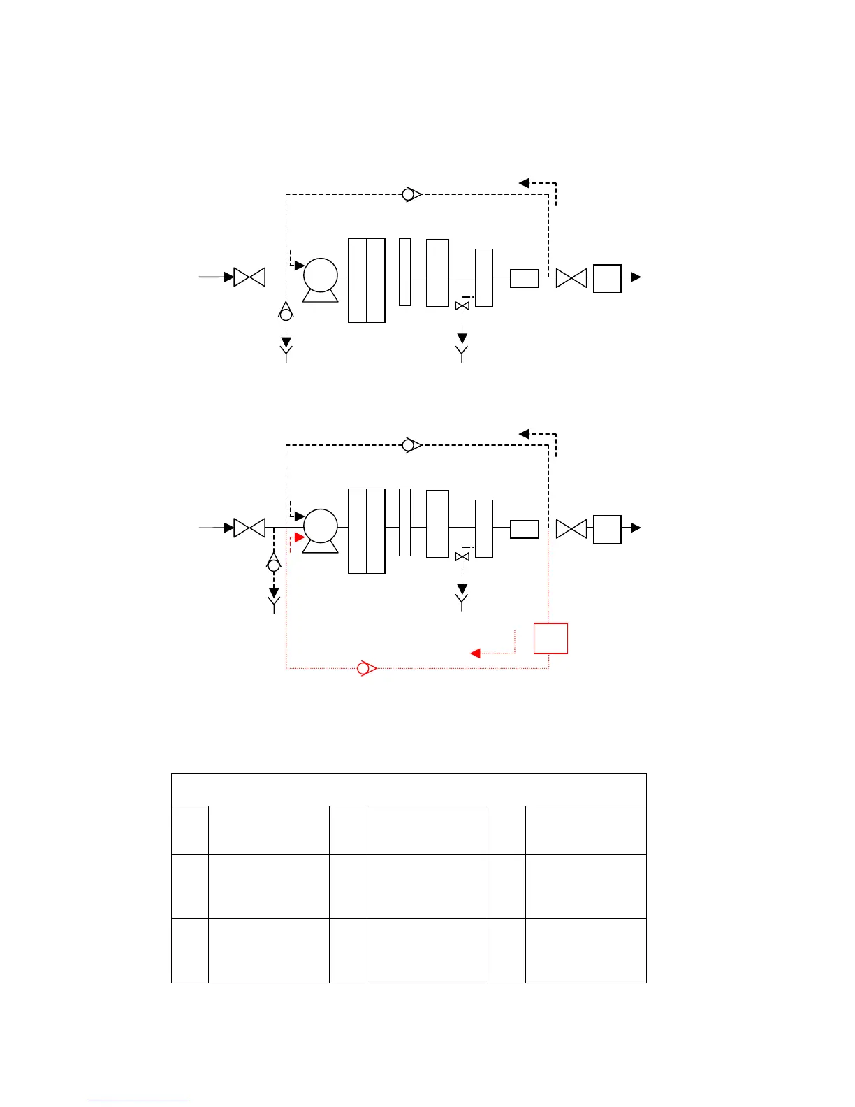
2-2 SCHEMATIC OF MAIN COMPONENTS
The water flow through a Milli-Q Synthesis Water Purification System is shown here in a flow diagram. A
description of each item is in the next section below.
The water flow through a Milli-Q Synthesis A10 is shown here in a flow diagram.
Identification of lettered items in the flow schematic above
A Inlet Solenoid
Valve
D UV Lamp and
Housing
G Resistivity
Sensor
B Pump E Quantum
Ultrapure
Cartridge
H Electric 2-way
Valve
C Q-Gard
Purification
Pack
F
Pyrogard
5000 UF
Cartridge
I Millipak
Membrane
Filter
FEEDWATER
A
B
C
D
E
MILLI-Q
PRODUCT