Checking Performance and Functions 5-15
Note:
1.
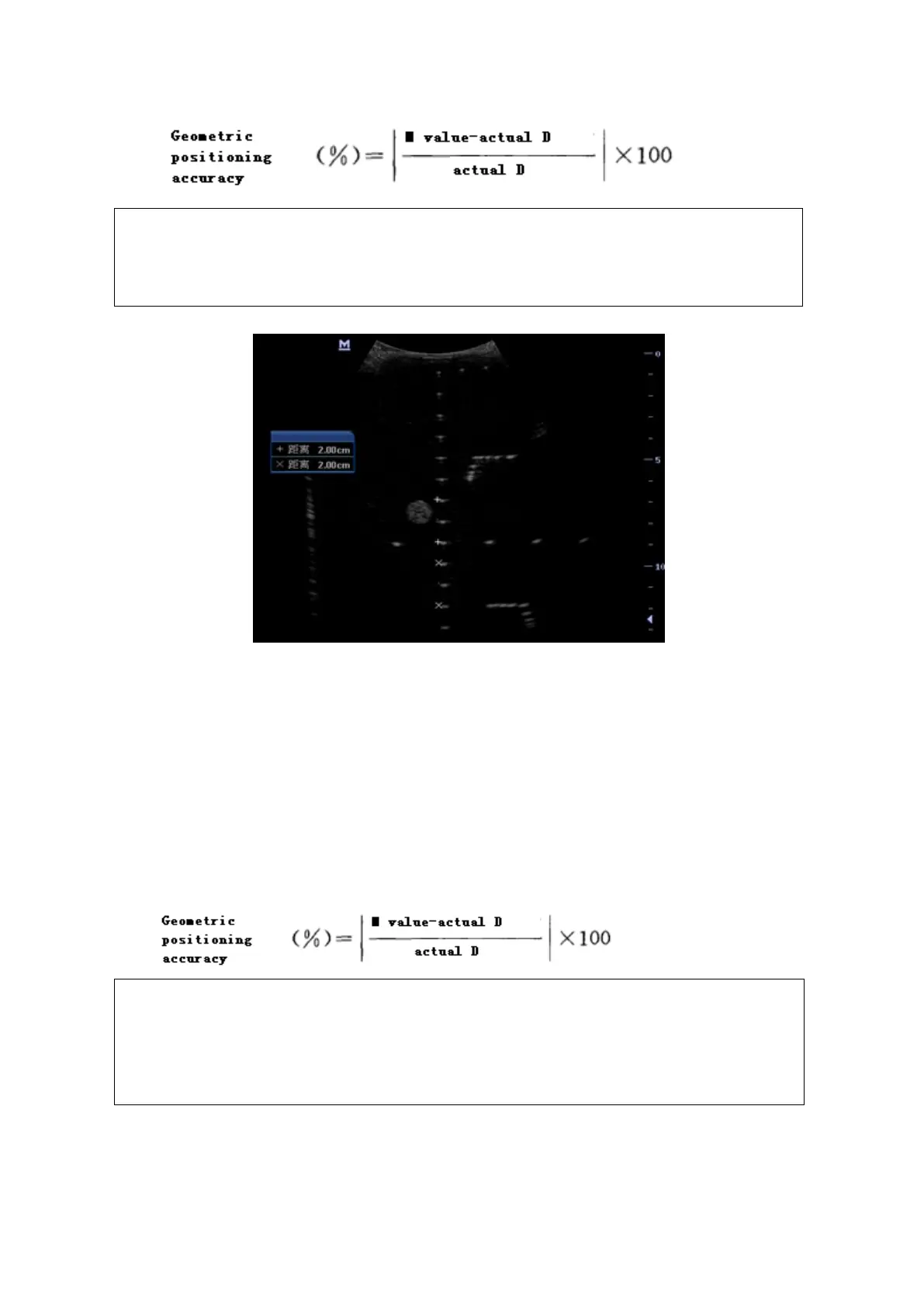
Measuring cursor should be placed on the top edge of the target image,
not in the middle or bottom edge.
2.
Scan plane should be perpendicular to each target line, in other words,
scan plane should be parallel to phantom section plane.
Image effect is show in figure below:
Lateral Geometric Positioning Accuracy
Test Procedure:
1. Place the probe gently on the acoustic window of phantom which is covered by water or gel.
2. Adjust display depth, to make horizontal groups display in the image.
3. Adjust focus to be in horizontal groups (no explicit standard).
4. Adjust gain, TGC, etc to make horizontal groups display clearly.
5. Use caliper to measure horizontal target distance by step of 20mm.
6. Select all measurement values deviating largely from 20 mm, and calculate the error by the
following formula.
Note:
1.
To linear array probe, read the lateral distance one segment after
another.
2.
For convex probe, display all lateral targets one time.
3.
The measurement caliper lies at the top or bottom of the target to be
measured.
Image effect is show in figure below: