Product Principle 4-1
4 Product Principle
4.1 General Structure of Main Unit’s
Hardware System
Master Board
Probe
Socket
Probe Board
TRA
FPGA
LCD Module
TR64 Board
AFE
AFE
64 Tx
(65~128)
CW
Module
TRB
FPGA
AFE
AFE
64 Tx
(1~64)
DSP
FPGA
System
monitoring
SM
(ARM)
COME Module
PHV Power Board
Control Panel
SSD
WiFi
LCD
Monitor
ECG Board
AC Adapter
Battery
Battery
AC
IN
DC
IN
POUT
128ch
POUT
64ch
Control
Power
4D&TEE
Signal
Control & Data Bus
XCVR
Control & Data Bus
XCVR
Power
Control
Signal
Clock
PowerLVDS
I2C
PCIE X4
PCIE X1
SATA
USB
Power
Power
Power
button
and
power
indicator
signal
Speaker
Power
Serial
port
DC-DC Module
4D&TEE
Communication
and control
USB 3.0
X2
HDMI
Pencil
Probe
Light Sensor
CLOCK
Fan
I2C
Power
supply
mgmt.
EC
(ARM)
PHV
(ARM)
Frontend
Backend
Power Supply
…
…
…
…
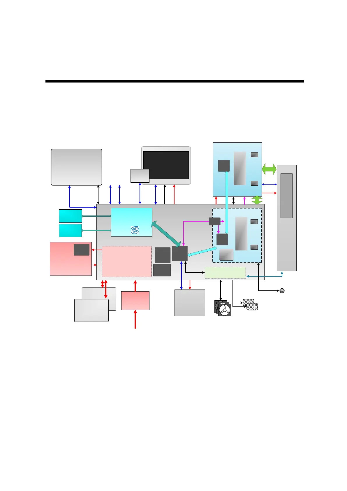
Figure
4-1 Schematic diagram of system hardwareThe general structure of M9’s hardware
system is shown in figure above. M9 system hardware consists of each following part:
Main board
DC-DC circuit, which offers power supply, charges or discharges the battery.
Functional circuit of back-end offers the functions of stereo audio, video audio, IO
interface, etc.
Signal processing FPGA. It processes the beamforming signal and occupies the
functional controls except for transmitting and receiving functions.