Product Principle 4-15
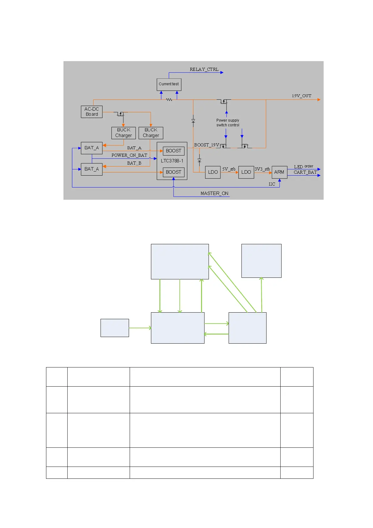
Principle diagram of management board of trolley battery is shown below:
Figure 4-14 Diagram of management board of trolley battery
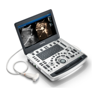
4.13 System Power-on Control
CPU module
Control for
starting/shutting
down device
Control
panel
S
3# S4#
POWER
_OK
Power
button
DC-DC
5VSTB
12V
Enabling
power
supply
3V3_STB
Function
circuit
Multi-
channel
power
supply
Figure 4-15 System power-on diagram
Description of related controlling signals:
No. Controlling signal Description Comme
nts
1 PWR_BTN_N,
PWR_BTN#
Pulse signal that power-on button of control panel
produces passes to CPU board through FPGA,
and is used for starting the device.
2 S3# Output by CPU board, effectively represents that
CPU system is in standby (the electrical level of
S4# is high) and keeps 5VSTB powered on when
it is in standby via FPGA.
3 S4# Output by CPU board, effectively represents that
CPU system is in dormancy.
4 S5# The signal is not used currently