4-16 Product Principle
5 PWR_OK# Sent out by power management FPGA to CPU
board, indicates that the 12V is powered on.
Power supply of main unit/battery enables the start of device.
Power supply produces 5VSTB and 3.3VSTB as the AC inputs.
Unplug AC when shutting down the device. Power supply cuts off 5VSTB output, but only
keeps the output of 3.3VSTB. Only with power button pressed again, it’s re-powered on.
Unplug AC when the device is in standby. Batteries, for standby usage, provide the output of
5VSBT and 3.3VSTB.
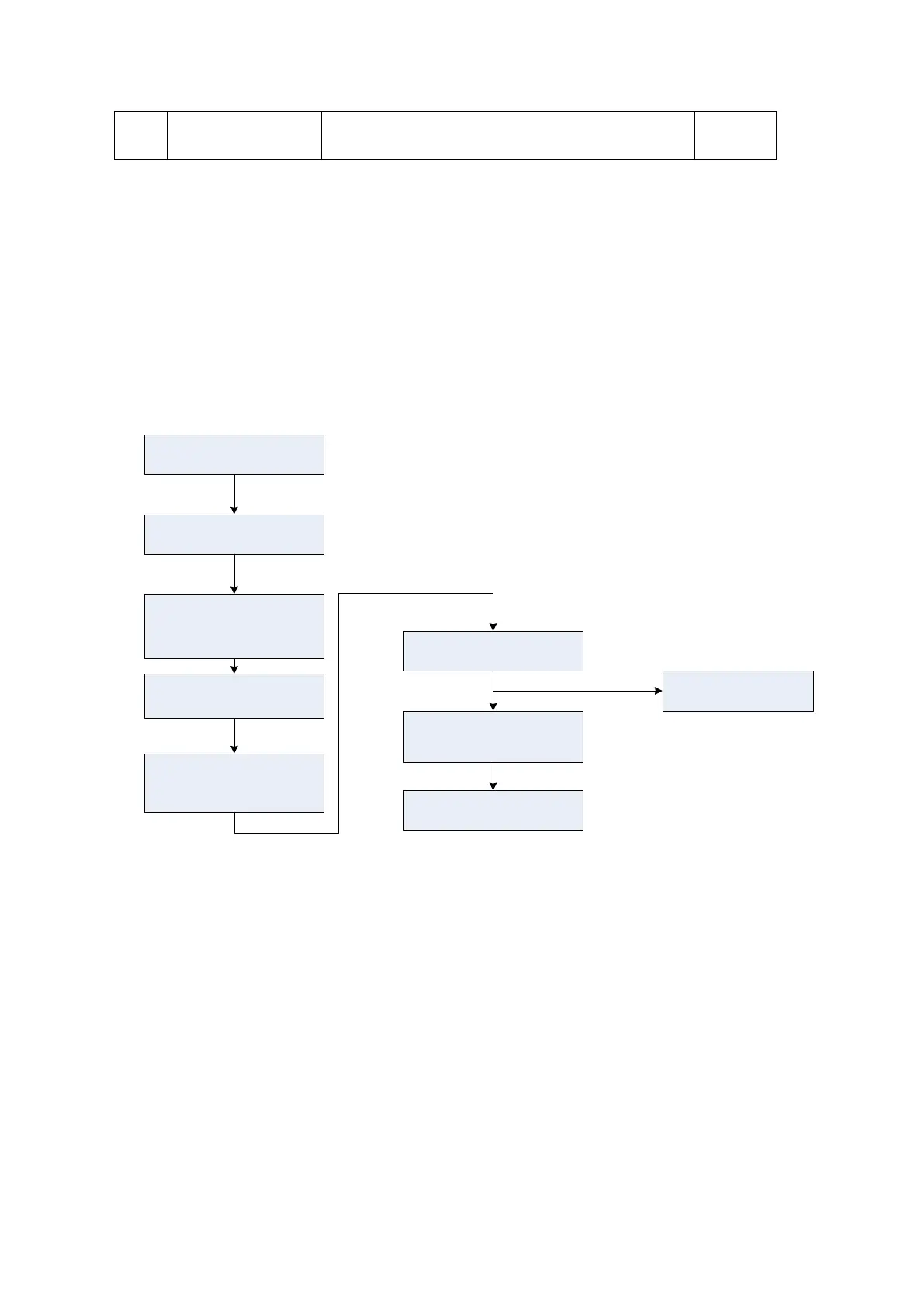
The process of power-on is shown below:
Connect to AC
Press power button
(control panel)
Receive valid
PWR_BTN_N
(power supply mgmt
FPGA)
Power supply mgmt
sends valid PWRBTN#
signal
S3# and S4#invalid
(COME module
sends)
DC-DC 12V power-on
PWR_OK valid
(power supply mgmt
sends)
CPU start
(COME module)
DC-DC board sends
power supply of other
circuits
Figure 4-16 Diagram of system power-on