6
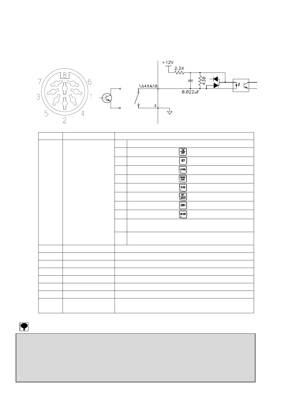
2-3. Connection of the external control input
The function can be controlled from the outside with the “INPUT” connector in the rear panel.
It is executed by shorting each pin and the COM pin with a contact point or an open collector after wiring for
the connector.
Pin No. Function No. Setting value and details
0
Operation OFF
1
The same operation as key
2
The same operation as key
3
The same operation as key
4
The same operation as key
5
The same operation as key
6
The same operation as key
7
The same operation as key
8
The same operation as key
9
Display the net weight
(Effective during the measurement mode.)
1
F-60
INPUT1 function
10
Display the accumulated value
(Effective during the measurement mode.)
2
COM pin of INPUT1~7
3 F-61 INPUT2 function Selectable as well as F-60
4 F-62 INPUT3 function Selectable as well as F-60
5 F-63 INPUT4 function Selectable as well as F-60
6 F-64 INPUT5 function Selectable as well as F-60
7 F-65 INPUT6 function Selectable as well as F-60
8 F-66 INPUT7 function Selectable as well as F-60
Connect
or case
Shield connection
Suitable plug : TCP0586-71-5201(by Hoshiden) or equivalent good.
● For the connections with external control inputs, be sure to apply shielded cable, and the shield should be connected with the connector
case. If not connected, it may cause malfunction due to the effects from external noises and so on.
● When “1 to 8” is selected in the setting of function F-60 to 66, each external control input becomes the same operation as the key input
operation.
● After about 100 ms or more is short-circuited, the operation is executed as for the input signal.
● Only the changeover of the net amount display and the changeover function of the accumulated display are the level input.
Other than them are pulse input and become effective once at the pulse width of 100 ms or more.
● Common of the COM of the external control input (two pins) and serial interface circuits is common.
INPUT
Layout of INPUT connector pin
CSD-904-EX internal e
uivalent circuit
or