3
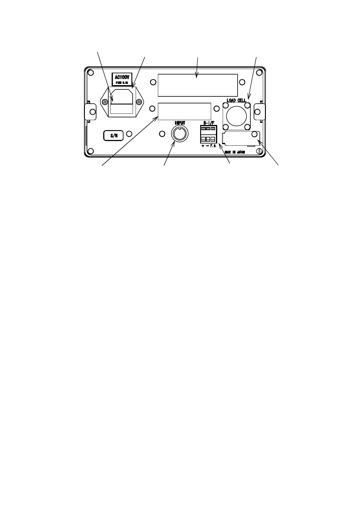
1-2. Rear panel
① Power supply socket
Connecting the AC cable regularly attached to this point, the power supply voltage is supplied.
② Fuse holder
The fuse of the specified capacity is installed.
③ Optional products attaching portion 1
One point of either the BCD output, RS-232C, RS-422/485, the analog electric current output or the
analog voltage output is installed.
④ Optional products attaching portion 2
The contact output is installed.
⑤ Connector for the external control input
It is an input connector to control the function of this unit with outside contact point or open collector.
⑥ Output terminals for serial interface
It connects with the printer or the external display unit.
⑦ Connector for load cell
It connects with the signal wires from the measuring section (load cell).
⑧ Calibration LOCK switch section
Calibration LOCK switch can be operated by removing the cover.
①Power supply socket
③Optional products
attaching portion 1
②Fuse holder ⑦Connector for load cell
⑥Output terminal for
serial interface
⑤Connector for external
control input
④Optional products
attaching portion 2
⑧Calibration LOCK switch section