74
13-3-10. Pin configuration of RS-232C connector
Pin No. Signal Name
1 CD
2 TXD
3 RXD
4 N.C.
5 S.G.
6 N.C.
7 RTS
8 CTS
9 N.C.
Suitable plug : DE-9S-NR by JAE or equivalent. ※Not attached.
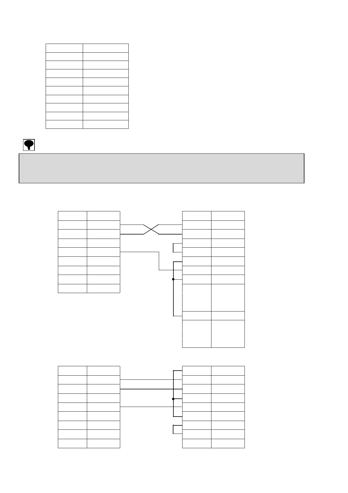
(1) Wiring of RS-232C No.1
CSD-904-EX
Host(25 pins)
1 CD
1 F.G.
2 TXD
2 TXD
3 RXD
3 RXD
4 N.C.
4 RTS
5 S.G.
5 CTS
6 N.C.
6 DSR
7 RTS
7 S.G.
8 CTS
8 DCD
9 N.C.
9
~
19
20 DTR
21
~
25
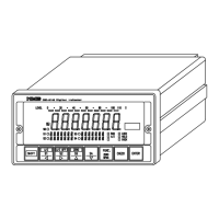
(2) Wiring of RS-232C No.2
CSD-904-EX
Host (9 pins)
1 CD
1 DCD
2 TXD
2 RXD
3 RXD
3 TXD
4 N.C.
4 DTR
5 S.G.
5 S.G.
6 N.C.
6 DSR
7 RTS
7 RTS
8 CTS
8 CTS
9 N.C.
9 RI
● The screws for the fixing base of plug at the connector of RS-232C interface is inch type thread.
● Don’t connect with N.C. pin.
● The internal circuit and photo-coupler is insulated.
● The external control input COM. (two pins) and S.G. for RS-232C are common.