18. Interface specifications
MiR1000 User Guide (en) 12/2020 - v.1.4 ©Copyright 2019-2020: Mobile Industrial Robots A/S. 196
Pin number Signal name Max. current Description
11 I1 PNP Input 1.
12 24V 1 A at 24 V Protected output.
13 I2 PNP Input 2.
14 24V 1 A at 24 V Protected output.
15 I3 PNP Input 3.
16 24V 1 A at 24 V Protected output.
17 Unassigned Unassigned.
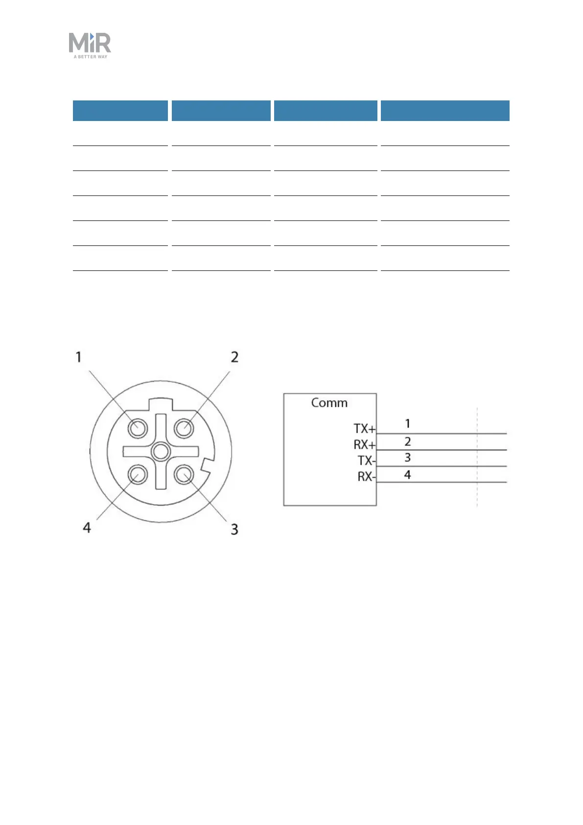
Ethernet
Figure 18.5. Ethernet connection. Pin numbers (left) and wiring diagram (right).
The communication interface is 10/100 Mbit Ethernet using a M12 connector—see
Connector list on page 201.
Various protocols are supported, such as Modbus. For more information on how to use
Modbus, ask your distributor for the guide How to use Modbus with MiRrobots.
 Loading...


