2. Product presentation
MiR1000 User Guide (en) 12/2020 - v.1.4 ©Copyright 2019-2020: Mobile Industrial Robots A/S. 25
Pos. Description Pos. Description
1 Ethernet 2 GPIO: General purpose I/O
3 Power 4 Auxiliary Emergency stop
5 Auxiliary safety functions
Table 2.4.
Identification of interfaces in Figure 2.10
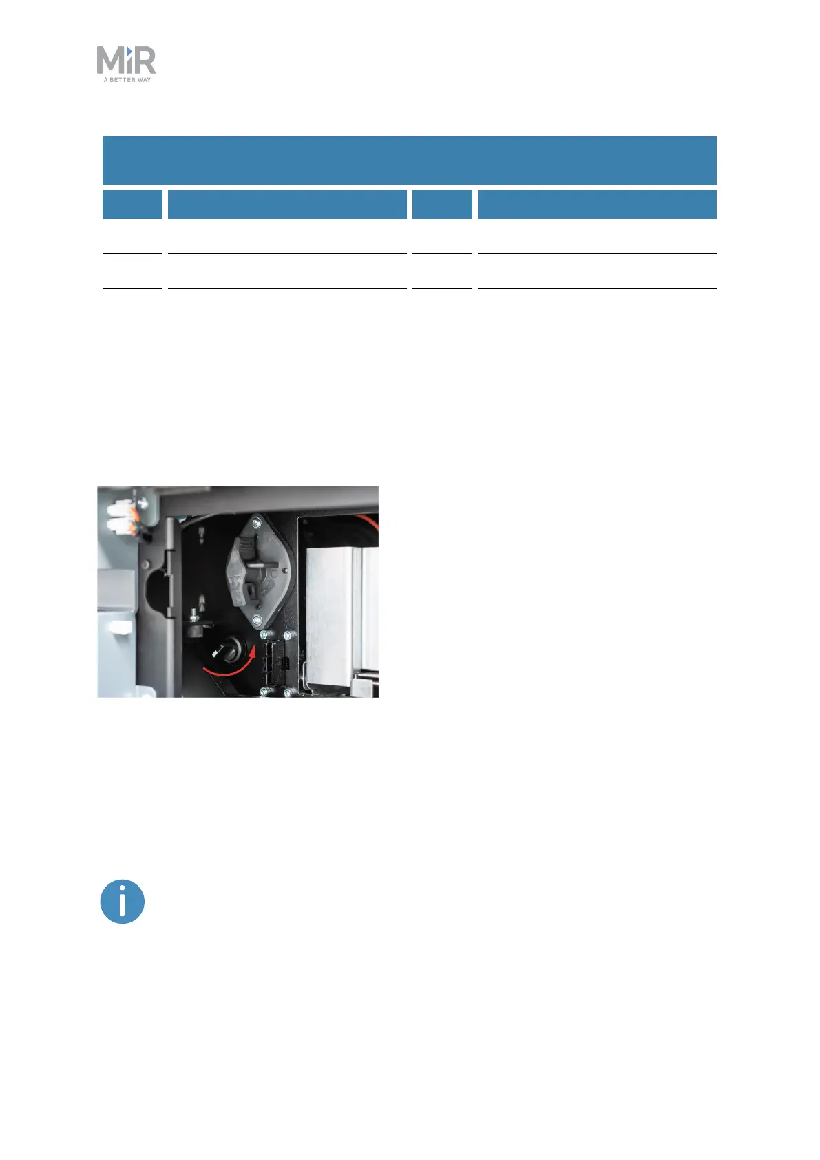
2.5 Manual brake release switch
The Manual brake release switch is located in the rear maintenance hatch below the Battery
disconnect switch. You release the robot's mechanical brakes by turning the Manual brake
release switch counter-clockwise.
Figure 2.11. The manual brake release switch is located below the control panel.
The mechanical brakes require electrical power to be released, so if the robot is without
power, the mechanical brakes cannot be released.
When driving in Autonomous mode, the robot engages and releases the mechanical brakes
automatically.
The robot cannot operate while the mechanical brakes are released manually.