10. Safety system
MiR1000 User Guide (en) 12/2020 - v.1.4 ©Copyright 2019-2020: Mobile Industrial Robots A/S. 95
1. The safety PLCfirst turns off the STOcontactors so power is cut from the motors.
To ensure that the STOcontactors switch states as expected, there is a
feedback circuit that connects to the safety PLC to verify that the
contactors switch to the correct state. When the robot is starting up, the
feedback circuit and STOcontactors are checked before allowing the robot
to be operated.
2. The safety PLCturns off the dynamic brake contactors to bring the robot to a stop.
3. The safety PLCmonitors data from the motor encoders to determine whether the robot
has stopped within the expected amount of time.
4. Once the robot has stopped, the mechanical brakes are engaged to keep the robot in
place, similar to the parking brake in a car.
The mechanical brakes are only intended to engage when the robot has stopped. Only when
the dynamic brake function does not stop the robot within the expected amount of time are
the mechanical brakes engaged to stop the robot while it is in motion. This is considered an
emergency situation where the dynamic brakes have failed, and an error is reported in the
robot interface. This can occur, for example, if the robot drives on surfaces that are not
within specifications or the load on the robot does not fulfill the payload specifications—see
Payload distribution on page 182.
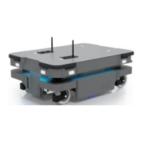
10.12 Light indicators and speakers
The robot uses two types of light indicators to let people in the environment know what the
robot is currently doing or planning to do.
• Status lights
LED light bands on all four sides of the robot uses colors and light motion patterns to
signal the current status of the robot.
• Signal lights
The signal lights at the front and back of the robot show if the robot is about to turn a
corner or go backward. Front lights are white and rear lights are red. Right and left turns
are indicated by blinking.