10. Safety system
MiR1000 User Guide (en) 12/2020 - v.1.4 ©Copyright 2019-2020: Mobile Industrial Robots A/S. 92
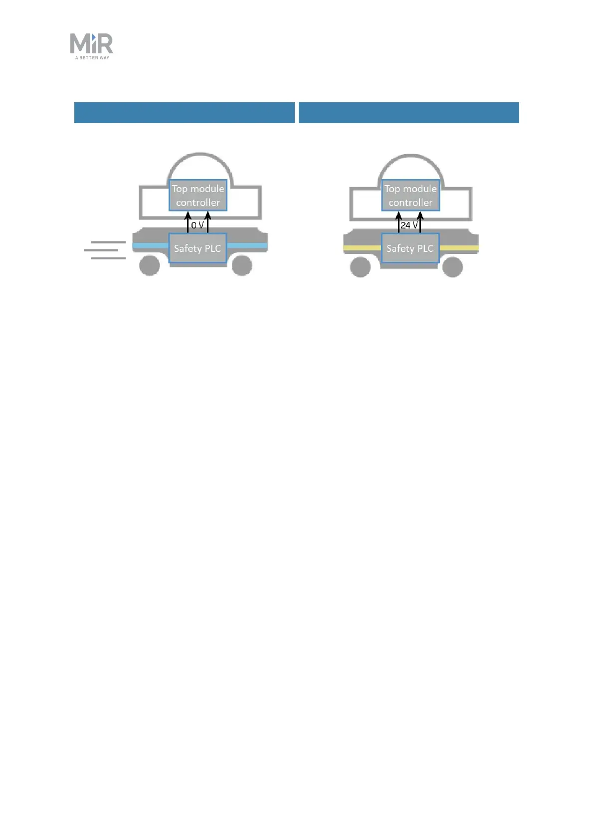
Signal when driving Signal when stopped
Figure 10.10. When the robot is driving, the safety PLC sends a 0 V signal to the top module through the
Auxiliary safety function interface. When the robot is stopped, the signal becomes 24 V.
Pins 5 and 6 in the Auxiliary safety function interface are used for the Locomotion function.
10.9 Shared emergency stop
The Shared emergency stop interface is used to control the Emergency stop state between
the robot and a top module. The interface has two inputs for bringing the robot into
Emergency stop and two outputs for signaling when the robot is in Emergency stop.
The outputs are used to signal to the top module that the robot is in Emergency stop. When
the robot is in an operational state, the outputs deliver 24 V. As soon as the robot enters
Emergency stop, they deliver 0V.
The inputs are used to enable the top module to bring the robot into Emergency stop. When
both inputs deliver 24 V, the robot can operate, but as soon as either or both of the inputs
deliver 0V, the robot enters Emergency stop.
These signals can be used if the top module has its own Emergency stop system and you
want both the robot and the top module to enter Emergency stop when either system is
triggered.
If the pins are unequally set for more than three seconds, the safety PLCregisters this as an
error in the system and needs to be reset before the robot can operate again. To do this, you
must restart the robot.