10. Safety system
MiR1000 User Guide (en) 12/2020 - v.1.4 ©Copyright 2019-2020: Mobile Industrial Robots A/S. 91
Signal to enable
operation
Signal to enter Protective
stop
Signal to enter Protective
stop
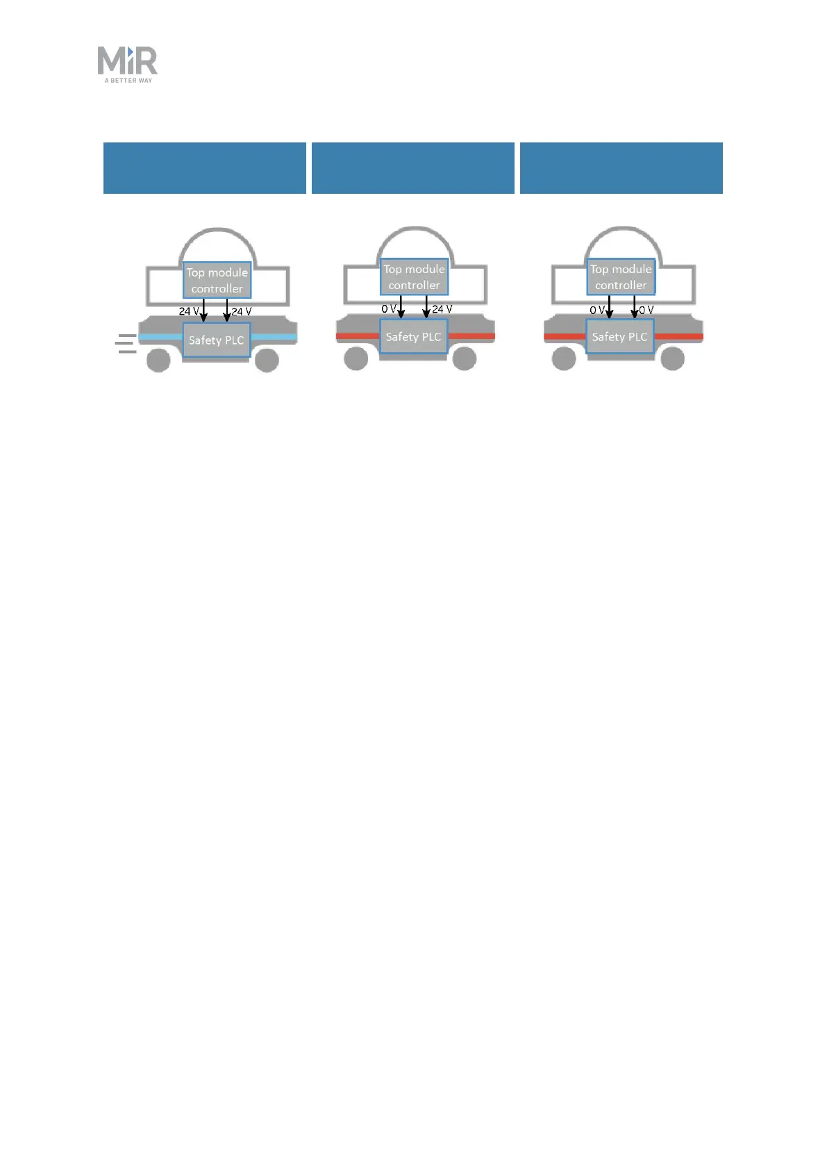
Figure 10.9. If both pins deliver 24 V to the robot, it can operate. If either or both of the pins deliver 0 V,the
robot enters Protective stop.
Pins 3 and 4 in the Auxiliary safety function interface are used for the Safeguarded stop
function.
10.8 Locomotion
The Locomotion interface is used to signal to a top module that the robot is driving. This
function uses two output pins, where both pins deliver 0 Vwhen the robot is driving and 24 V
when the robot is stopped. You can use this interface to make your top module behave
differently depending on whether the robot is driving or not. The interface is intended to be
used to ensure that the top module is programmed to go into a safe state when the robot is
driving. For example by engaging the brakes in any actuators that may result in injury to
personnel.