9. Navigation and control system
MiR1000 User Guide (en) 12/2020 - v.1.4 ©Copyright 2019-2020: Mobile Industrial Robots A/S. 68
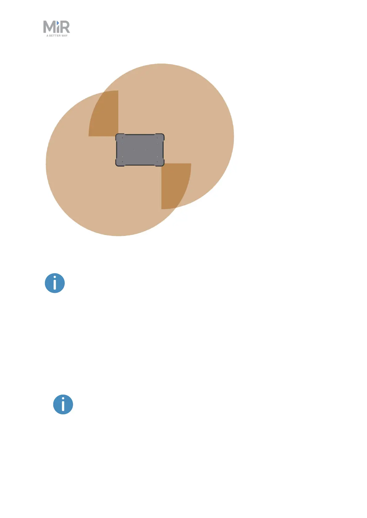
Figure 9.7. The two safety laser scanners together provide a full 360° view around the robot.
When mapping, the safety laser scanners' view is reduced to 20 m to ensure
that maps get the highest possible quality.
The laser scanners have the following limitations:
• They can only detect objects that intersect a plane at 200 mm height from the floor.
• They do not detect transparent obstacles well.
• The scanner data can be inaccurate when detecting reflective obstacles.
• The laser scanners may detect phantom obstacles if they are exposed to strong direct
light.
If you are using the robot in an area with walls made of glass or reflective
material, mark the walls as Forbidden zones on the map, not as walls—see
Creating and configuring maps on page 102. Walls on the map that the
robot cannot detect will confuse the robot's navigation system.