20
Mechanical Installation
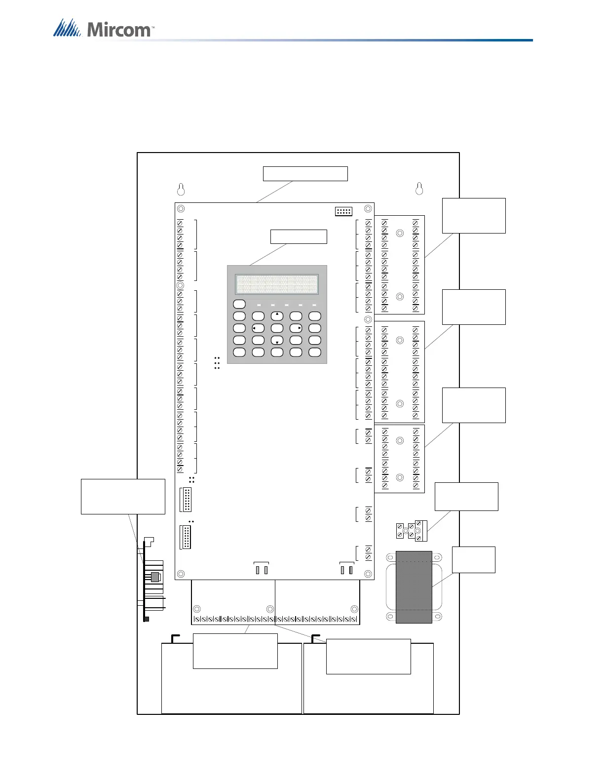
5.3 Installing the Adder Modules
FA-300 series fire alarm panels come pre-assembled with all components and boards except
for adder modules. Module installation locations are shown in Figures 6 and 7. Refer to "6.1.1
Connectors and Jumpers on the Main Fire Alarm Board" on page 24 for jumper or DIP switch
settings and see "7.6 Wiring Tables and Information" on page 37 for wiring information.
Figure 6 Installation of adder modules for FA-301 LCD
S-+NC N OCNC NOCNC NOCNC NOC
+-+-COM(+)
COM(-)
TRLTRB RTRT RTR T
RES CO RES C O
LINE1LINE 2
JW3
JW2
JW1
-+-+-+-+-+-+-+-+-+-+-+-+-+-+-+-+
DET 1DET 2DET 3DET 4DE T 5DE T 6DE T 7DE T 8DET 9DET 10DET 11DET 12SI G 1SIG 2SIG 3SIG 4
JW 6
JW 5
JW 4
TO PR -300 MO D ULE
T O R M-312/R M-306 RELAY
MODU LE
RS -
485
AUX. REL AYALA RM
RELAY
SU P E RV IS O RY
RELAY
TR OUBLE
RELA Y
AU X
SUPPLY
4- W IR E
SUPPLY
UNFILTERED
RTI
PORT
P
1
P
2
P
3
P
4
+
_
BATTERY SEC. TX
BATTERY BATTERY
CLASS -A converter
board for detection
circuits ICAC-306 (6
cir cuits )
CLASS -A converter
board for detection
circuits ICAC-306 (6
cir cuits )
CLASS -A converter
board for indicating
circuits OCAC-304
(4 circuits)
Reverse polarity and city
tie module PR-300.
Mounted on hex spacer
with two screws provided
Relay Module RM-306
Mount relay module on the
left side using two screws
provided .
Relay Module RM-312
centre under main fire
alarm board using three
screws provided .
Transformer
Fuse and AC wirung
terminal
MAIN FIRE PANEL BOARD
SY ST EM
RESET
SIGNAL
SI L EN C
E
FI R E
DRILL
B U ZZER
SI L EN C
E
LA M P
TEST
1
4
7
*
2
5
8
0
3
6
9
#
EN T ER
MENU
CANCEL
INFO
ABC DEF
GHI JKL MNO
PR S
TUV
WXY
QZ
A.C. O N ALAR M SUPV TR BL CPU FA IL
SYSTEM NORMAL
18:01 MON 2003-04-05
LCD DISPLAY
Fuse and AC
wiring terminal