40
Turning on the Panel
8.2 Connecting the Power
After completing the steps in "8.1 Before Connecting the Power" on page 39:
1. Plug in the AC power.
The A.C. ON LED illuminates, the Common Trouble LED flashes, and the buzzer
sounds.
2. Press the SYSTEM RESET button.
The buzzer continues to sound and the Common Trouble LED continues to flash.
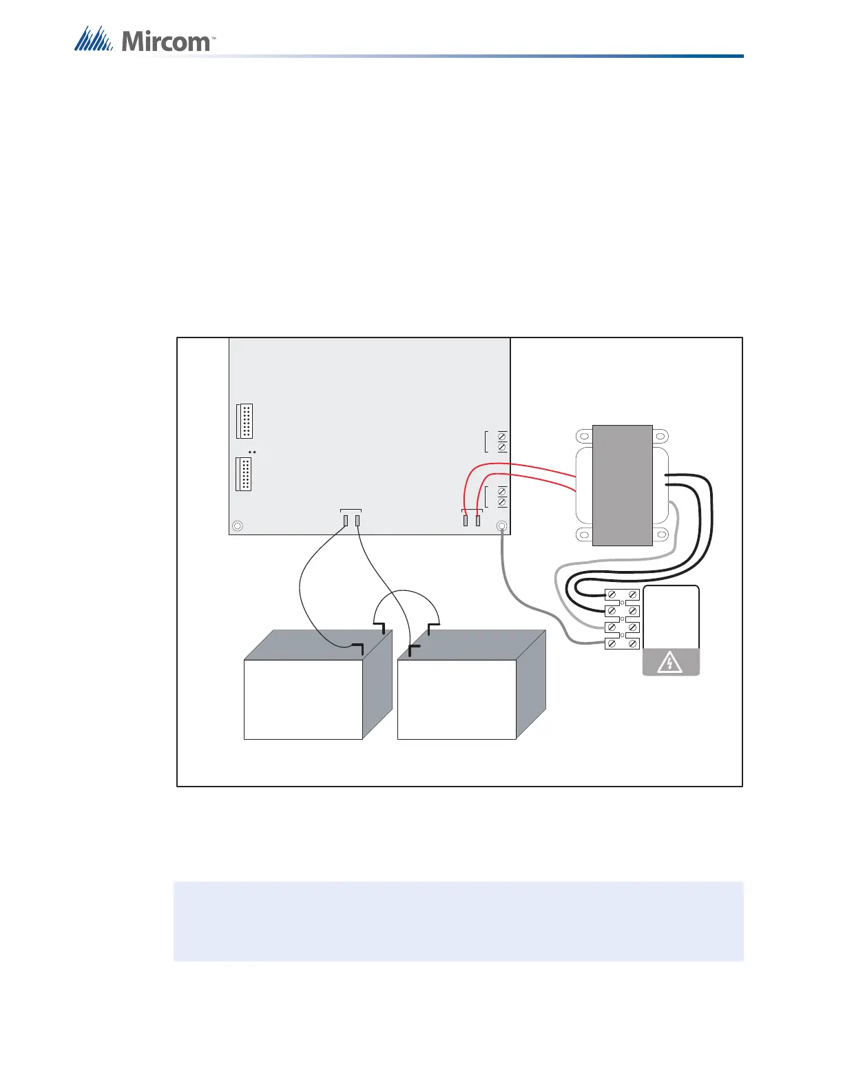
3. Connect the batteries as shown in Figure 27. Observe the correct polarity: the red wire is
positive (+) and black wire is negative (-).
Figure 27 Battery connections
All indicators should be off except for the green A.C. ON LED and the green TROUBLE
LED in the lower left corner of the main board.
4. Configure the Fire Alarm Control Panel as described in "11.0 Configuration" on page 52.
Note: The green TROUBLE LED in the lower left corner of the main board is illuminated
when the system is normal. This LED is for diagnostics and indicates that the
Trouble Relay is in normal standby condition.
JW1
-+-+
SIG 3SIG 4
TO PR- 30 0 MO DULE
TO RM-312/RM-306 RELAY
MOD U LE
P1 P2
P3 P4
+
_
BATTERY
SEC. TX
blk
red
red
red
red
blk
+
+
_
_
Battery Battery
NOTE: TO PREVENT SPARKING, CONNECT BATTERIES AFTER THE
SYSTEM MAIN A.C. POWER IS TURNED ON
red
green
blk
yellow
240 VAC 50Hz
120 VAC 60Hz
N
GND