30
Field wiring
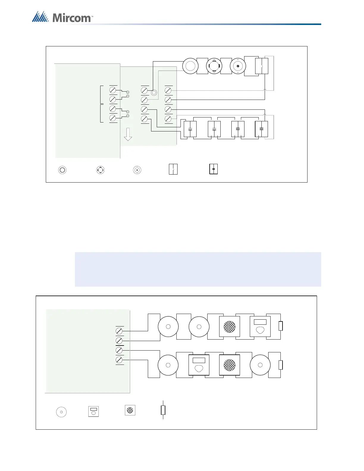
Figure 17 Initiating circuit– Class A or Style D wiring
7.1.2 Indicating Circuit Wiring
The FA-300 Series Fire Alarm supports Class B or Style Y and Class A Style Z wiring for its
indicating circuits. Each circuit is supervised by a 3.9 k
Ω end-of-line resistor. Each indicating
circuit provides up to 1.7 A, 5 A maximum total if no auxiliaries are used.
Figure 18 Indicating circuit – Class B or Style Y wiring
Note: An active end-of-line resistor cannot be used with any indicating circuits. Always
use 3.9 k
Ω end-of-line resistors for indicating circuits.
+
-
STYLE D
WIRING
STYLE D
WIRING
INITIATING
CIRCUIT #1
INITIATING
CIRCUIT #2
INITIATING
CIRCUIT - 1
ALARM
ZONE
INITIATING
CIRCUIT - 2
SUPERVISORY
ZONE
ION SMOKE
DETECTOR
PHOTO
SMOKE
DETECTOR
HEAT
DETECTOR
PULL STATION
SUPERVISORY
4 MORE INITIATING
CIRCUITS NOT SHOWN
DCAC-306 CLASS A
CONVERTER MODULE
FIRE ALARM MAIN BOARD
BLK RED
BLK RED
- DET1
OUT+
- DET2
OUT+
- DET1 RET+- D ET 2 R E T +
+
-
DET 1DET 2
- SIG 1 +
STYLE Y
WIRING
STYLE Y
WIRING
INDICATING
CIRCUIT - 1
INDICATING
CIRCUIT - 2
BELL STROBE 3.9K 1/2 WATT ELR
INDICATING
CIRCUIT #1
INDICATING
CIRCUIT #2
HORN
FIRE ALARM MAIN BOARD
- SIG 2 +