32
Field wiring
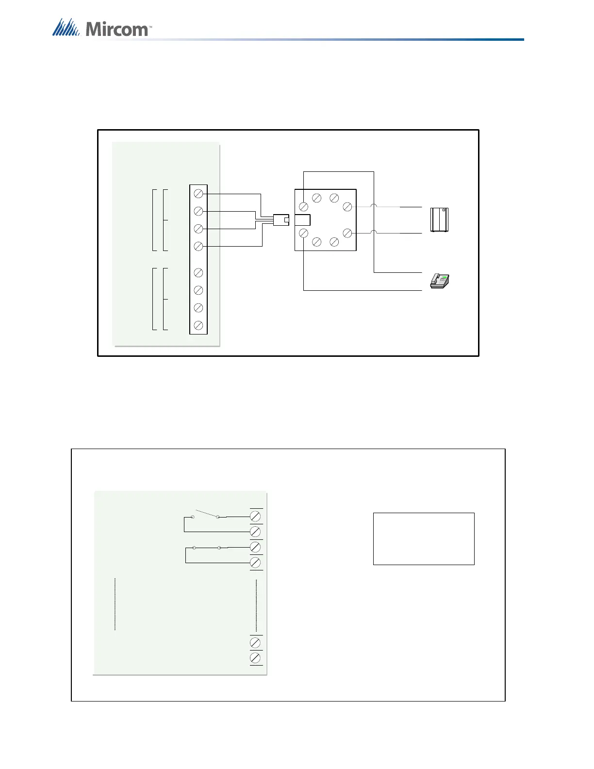
7.1.4 Dialer Wiring
If you have Fire Alarm Panel Models FA-301-12LDW, FA-301-12LDR, and FA-301-8LDW
there is a dialer on board and terminals marked Line 1 and Line 2 must be wired as shown in
Figure 21 below.
Figure 21 Dialer wiring
7.2 Relay Adder Module Wiring
Wire relays on the relay adder modules RM-312 and RM-306 as shown in Figures 19 and 20.
Figure 22 Relay per zone (RM-312) Terminal connection
TIPTIP RIN GRING
premise telephone
IF permitted
TIPTIP RIN GRING
LINE-1
LINE-2
1
23
4
8
5
76
Public switch
Telephone company
wiring
TIP
RING
TIP
RING
RJ 31X
BROWN
GREY
GREEN
RED
COCO RESRES
Line 2 is Wired as shown for Line 1
FIRE ALARM MAIN BOARD
C
C
NO/NC
NO/NC
C
NO/NC
ALL RELAY CONTACTS
28V DC, 1 AMP
RESISTIVE LOAD
RM-312 12 RELAY ADDER MODULE
NORMALLY OPEN OR
NORMALLY CLOSED
CONNECTION IS
SELECTED BY JUMPER
ON RELAY BOARD.
NOTE: ALL RELAY CIRCUITS ARE POWER
LIMITED AND MUST USE TYPE FPL, FPLR or
FPLP POWER LIMITED CABLE.
NORMALLY OPEN
CONNECTION
NORMALLY CLOSE
CONNECTION
RELAY
CIRCUIT #1
RELAY
CIRCUIT #2
RELAY
CIRCUIT #12