42
9.0 Indicators, Controls and Operations
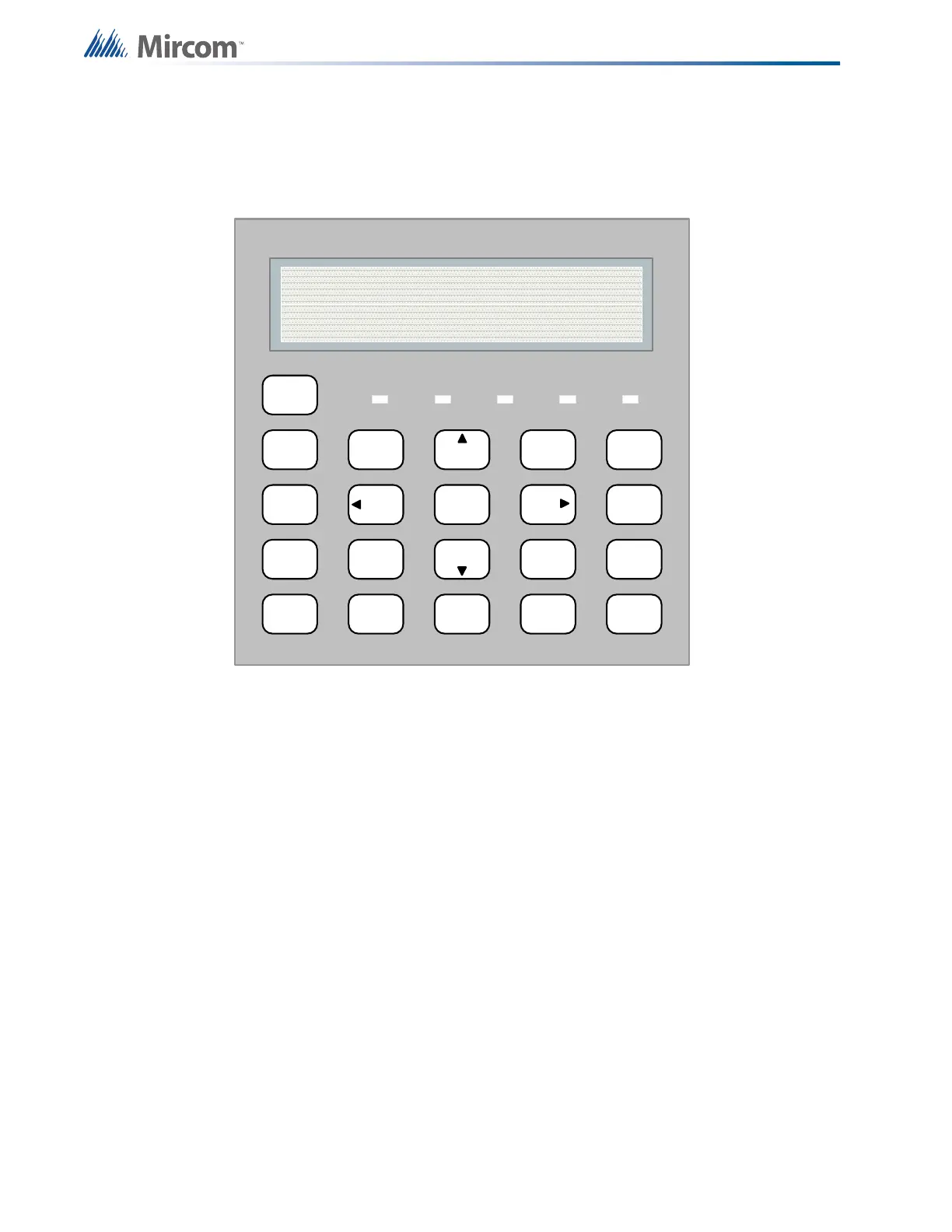
Refer to Figure 28 below which shows the LCD Display, the Keypad and Control Button
locations.
Figure 28 LCD Display and control buttons
The Main Display Panel on the Main Fire Alarm Control Board consists of:
• 5 common LED Indicators (under the LCD display)
• 5 Common Buttons (column left of key pad)
LED Indicators may be Amber, Red, or Green, and may illuminate continuously (steady), or at
one of two Flash Rates.
• Fast Flash (Supervisory)- 120 flashes per minute, 50% duty cycle
• Trouble Flash (Trouble)- 20 flashes per minute, 50% duty cycle
9.1 Common Indicators
9.1.1 Buzzer
The buzzer is activated by any of the following events:
Fire Alarm Steady
Supervisory Alarm Fast Flash
Trouble Trouble Flash Rate
SYSTEM
RESET
SIGNAL
SILENCE
FI RE
DRILL
BUZZER
SILENCE
LAMP
TEST
1
4
7
*
2
5
8
0
3
6
9
#
ENTER
ME NU
CANCEL
INFO
ABC DEF
GHI JKL MNO
PRS
TUV
WXY
QZ
A.C. ON ALARM SUPV TRBL CPU FAIL
SYSTEM NORMAL
18:01 MON 2003-04-05