Lobby Control Unit Setup
Version 5.4 TX3 Telephone Access System Installation and Operation Manual 51
LT-969 Copyright 2019
JW11:
• If the panel has the MC-001 microphone, close JW11.
• If the panel has the MC-012 or MD-1243 microphone, open JW11 (this is
the default setting).
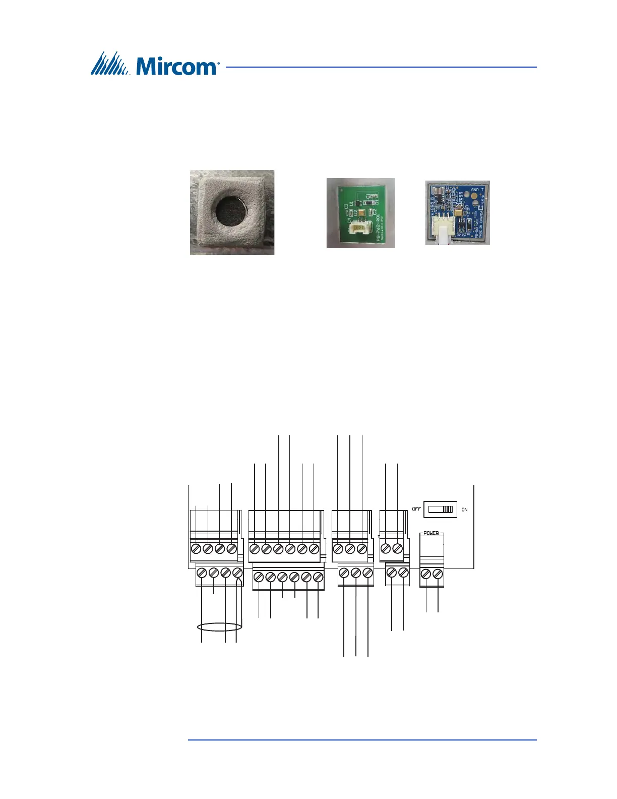
Figure 28 Microphones and JW11
4.2 Controller Board Connectors - Bottom
Figure 29 shows the connectors at the bottom of MD-1245, the lobby controller
that has a 4-pin terminal block for the microphone. This board is present in
models ending in -C.
Figure 29. Controller Board Connectors on MD-1245 - Bottom
MC-012 microphone
JW11 off or open
MC-001 microphone
JW11 on or closed
MD-1243 microphone
JW11 off or open
Input 3
Input 5
Camera Supply
Power Supply for TX
3
RS-485 OUT
+
+ -
- s +
RS-485 IN
- s +
- +
+
-
+-
+-
Speaker
Connection
-
White
MD-1243 Microphone
Connection
Red Black
+
-
+
-
Input 2 Input 4
Unused
Unused
Unused
Sheild