52 TX3 Telephone Access System Installation and Operation Manual Version 5.4
LT-969 Copyright 2019
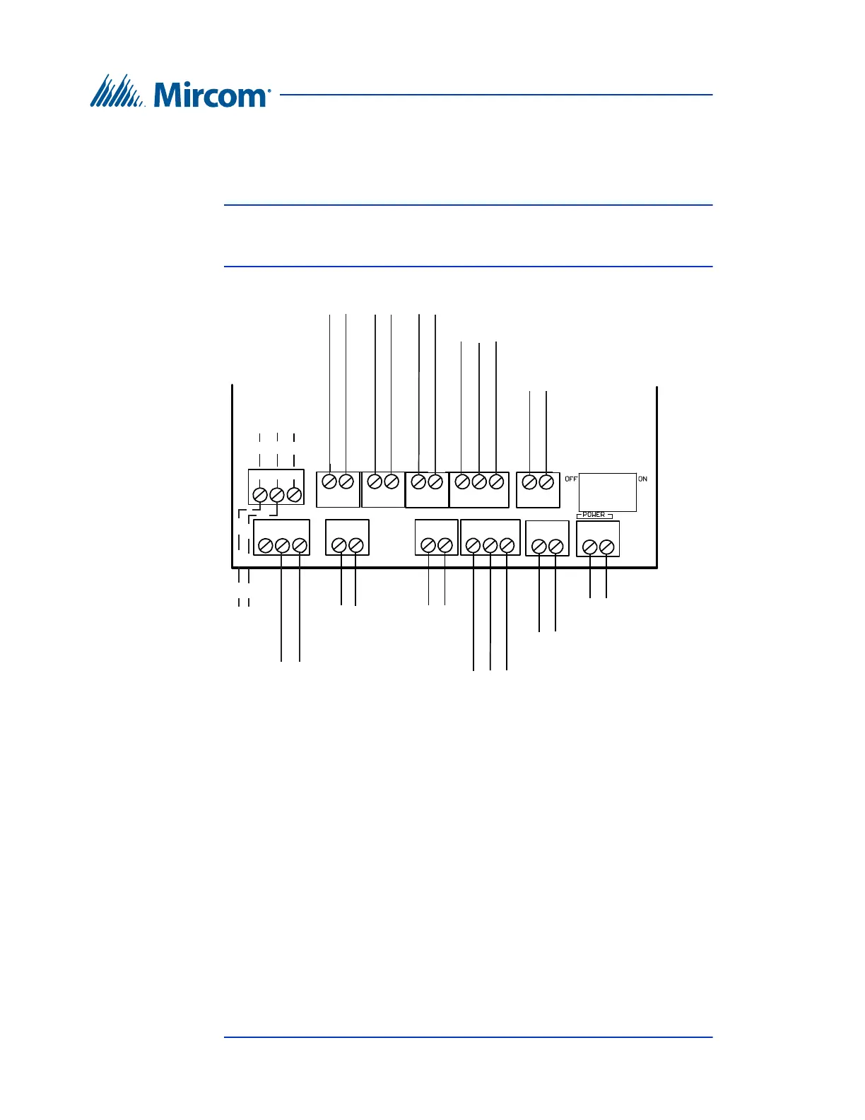
Lobby Control Unit Setup
Figure 30 shows the connectors at the bottom of MD-1086, the lobby controller
that has a 3-pin terminal block for the microphone. This board is present in Touch
Screen models that do not end in -C, for instance TX3-1000-4U-B.
Note: Both models of microphone are shown in figure 30. Connect only
one microphone at a time, and set JW11 correctly depending on the
microphone. See section 4.1.4 on page 50.
Figure 30. Controller Board Connectors on MD-1086 - Bottom
4.2.1 Microphone Connection
The microphone connection is situated at the bottom left of the main controller
board. It connects to the front display and is factory set.
4.2.2 Speaker Connection
The speaker connection is situated at the bottom left of the main controller board.
It connects to the front display and is factory set.
LED/LAMP
Supply
Speaker
Connection
Input 1
Input 2 Input 3 Input 4
Input 5
Camera Supply
Power Supply for TX
3
(use 18 AWG)
RS-485 OUT
- +
- +
RS-485 IN
- s +
- +
- +
+--++-
+-
+-
MC-001
Microphone
Connection
RWB
MC-012
Microphone
Connection
- s +