Lobby Control Unit Setup
Version 5.4 TX3 Telephone Access System Installation and Operation Manual 55
LT-969 Copyright 2019
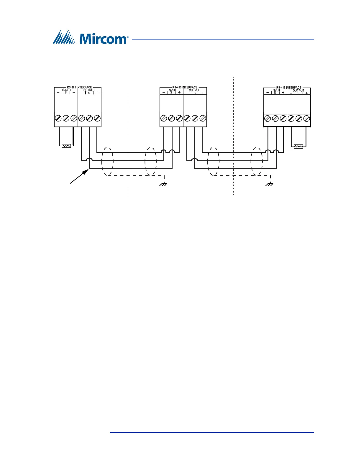
Figure 32. RS-485 Wiring
4.2.5 Auxiliary Camera Supply
The camera supply connection is situated at the bottom right of the main
controller board and provides + 12 Vdc, 600 mA. The camera is controlled by
one of the general outputs. The camera’s positive terminal connects to the
normally open (NO) general output relay contact. The common (C) contact of the
general output relay connects to the + 12 Vdc supply terminal. The camera is
typically configured to operate when the main door is open.
4.2.6 LED/Lamp Supply
The LED/Lamp connection is situated at the bottom right of the main controller
board. This lamp is used with the paper directory models to illuminate the paper
directory.
Connect shield to chassis
ground on one panel only
Connect shield to chassis
ground on one panel only
120 Ω
120 Ω
Optional common
reference connection
if available
Panel 1
First panel on network
Panel 3
Last panel on network
Panel 2