78 TX3 Telephone Access System Installation and Operation Manual Version 5.4
LT-969 Copyright 2019
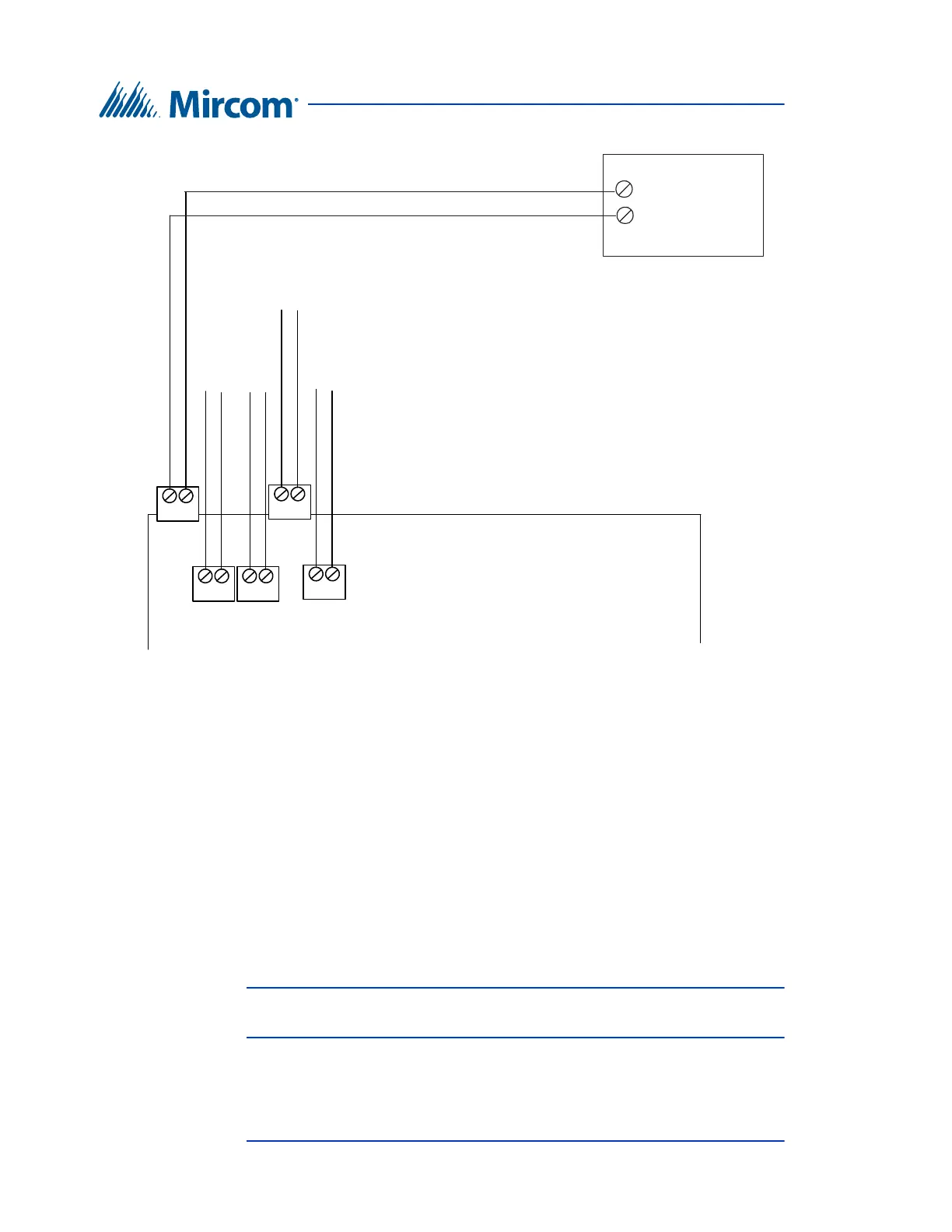
NSL Relay Cabinet Installation and Wiring
Figure 45. NSL Controller Telephone Lines
To test the TX3-8M-NSL Relay Control unit
1. Connect a telephone to the TX3-8M-NSL Relay Control unit telephone
terminal block (see figure 43).
2. Pick up the telephone. A dial tone is heard.
3. Dial *RRRR#, where RRRR is the relay code. A resident line LED relay
card light turns on.
4. Hang up. The resident line LED relay card light turns off. The TX3-8M-
NSL Relay Control unit is operational.
5. Perform the same test for all of the relay codes.
Note: Resident telephones associated with the relay card will ring. If the
resident picks up their telephone a connection will be established.
6. Disconnect the telephone and procedure with the installation.
Telephone Lines 1 to 5
Line 1
T R
Line 2
T R
Line 3
T R
Line 5
T R
Line 4
T R
Line 1
R
T
TX3 Lobby Panel Main
Controller Board
TX3-NSL-8M Relay
Control Unit
1
2
3
4
5