NSL Relay Cabinet Installation and Wiring
Version 5.4 TX3 Telephone Access System Installation and Operation Manual 81
LT-969 Copyright 2019
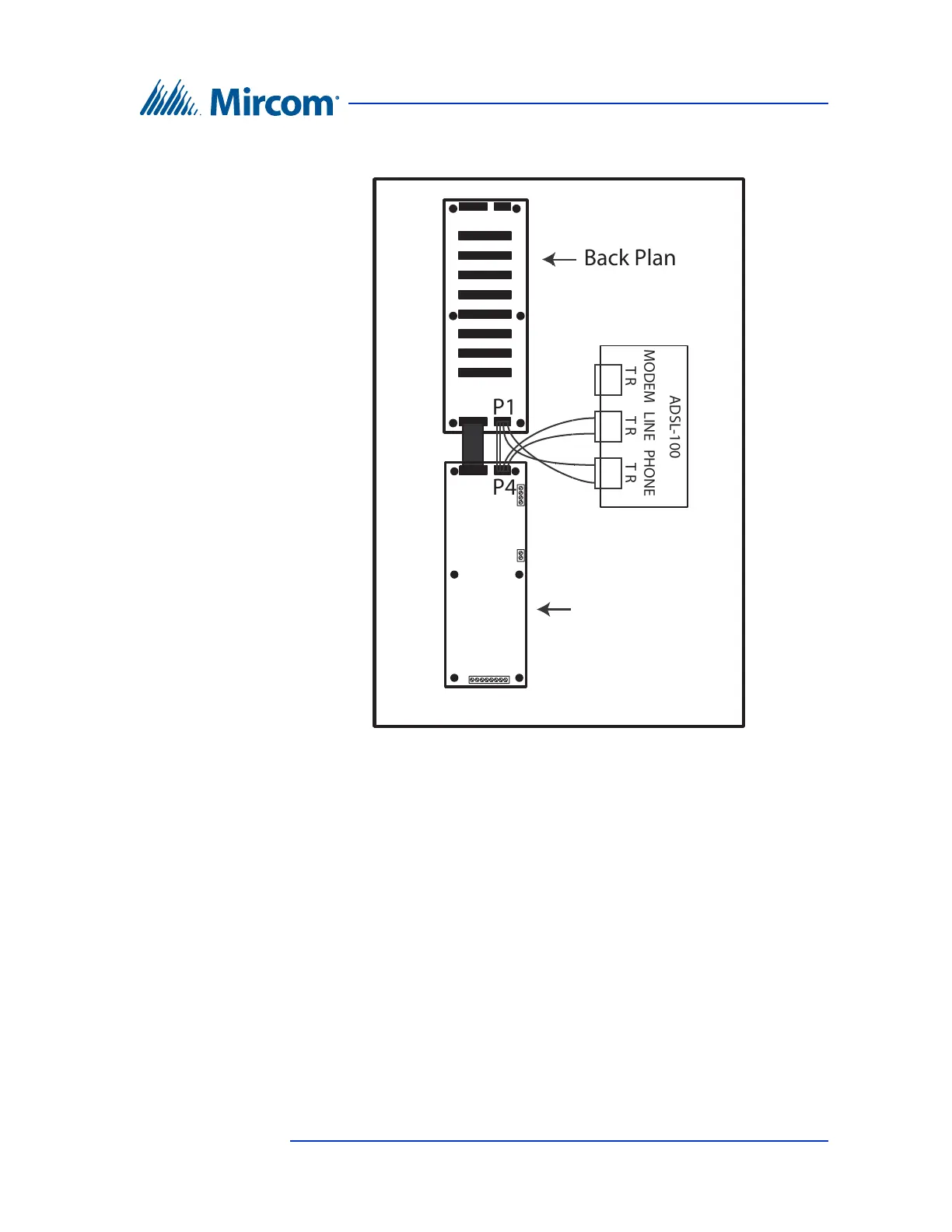
Figure 47. ADSL-100 Filter Module Installation
5.3.10 Setting the Backplane Number
Relay addresses are numbered to show the relay card’s connector location and
backplane number setting. Table 4 provides sample addresses for the first three
backplane number jumper settings.
For example, when the backplane number jumper setting is set to 1, the first relay
on P3 relay board has an address of 1. When the backplane number setting is set
to 2, the first relay on P3 relay board has an address of 97.
To set the backplane number
1. Determine the relay address according to the relay card’s connector
location and backplane number setting.
NSL Controller
P4
P1
LINE
T R
PHONE
T R
MODEM
T R
ADSL-100
Back Plane
Line to P4 on NSL Controller
Phone to P1 on Back Plane