NSL Relay Cabinet Installation and Wiring
Version 5.4 TX3 Telephone Access System Installation and Operation Manual 83
LT-969 Copyright 2019
5.3.11 2012 NSL Relay Board Wiring
The 2012 NSL Relay Board plugs into the backplane boards of the NSL units.
There may be up to eight relay boards in each backplane board (to a maximum of
128 relay boards for 16 NSL backplane boards).
In each NSL backplane the relay boards are numbered 1 to 8, starting from the
bottom of the backplane and going to the top. Each relay board provides 12
resident telephone lines connections, for a maximum of 1536 telephone lines per
system.
Connections are made via the CA-71A BIX Block or RJ-71C Punch Down Block
Wiring Configuration as follows:
CA-71A BIX Block. The CA-71A (for Canada) wiring configurations of BIX
and Punch Down Block are shown in figure 50 and table 5.
RJ-71C Punch Down Block. The RJ-71C (for U.S.A.) wiring configurations of
BIX and Punch Down Block are shown in figure 51 and table 6.
Normally, the required blocks are installed by the telephone company. Each
block serves up to 12 telephone lines.
The 50-pin amphenol connector on the BIX block connects to the 2012 relay card
using the standard 9106 cable.
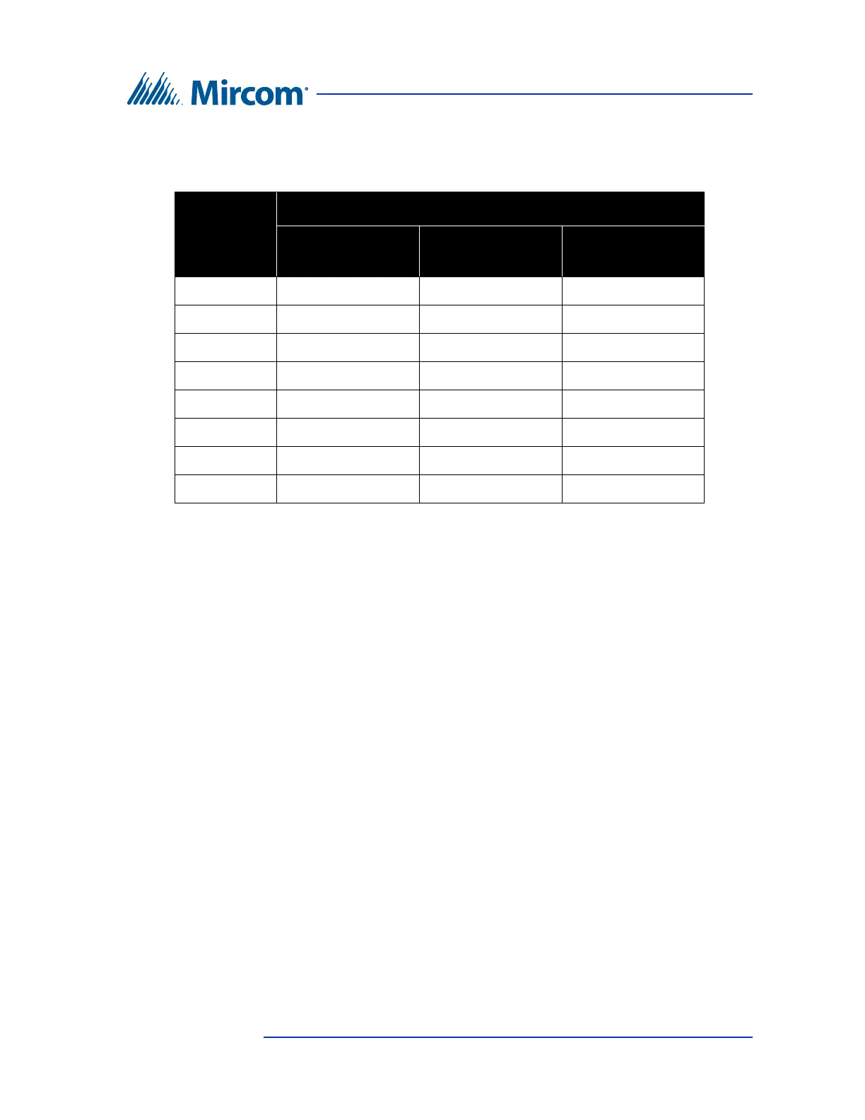
Table 4: Sample Backplane Relay Addresses
Connector Backplane Number Setting
Jumper 1
Address 1-96
Jumper 2
Address 97-192
Jumper 3
Address 193-288
P3 1 to 12 97 to 108 193 to 204
P4 13 to 24 109 to 120 205 to 216
P5 25 to 36 121 to 132 217 to 228
P6 37 to 48 133 to 144 229 to 240
P7 49 to 60 145 to 156 241 to 252
P8 61 to 72 157 to 168 253 to 264
P9 73 to 84 169 to 180 265 to 276
P10 85 to 96 181 to 192 277 to 288