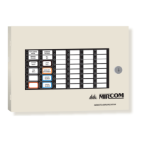
Touch Screen Factory Wiring
TX3 Touch Screen Installation Manual 117
4.2 Factory Wiring for Models Ending in -C
In these diagrams, MD refers to the Mircom part numbers of the circuit boards,
and WX and WR refer to the Mircom part numbers of the cables.
4.2.1 Factory Wiring for TX3-TOUCH-S15-C and TX3-TOUCH-F15-C
Figure 111. Factory connections on the audio mixer board for
TX3-TOUCH-S15-C and TX3-TOUCH-F15-C
Figure 112. Factory connections on the power button
WX-079: CN31 on PC board
WX-109: TS2 on telephone
access controller (not
polarity sensitive)
WR-21160 and WR-21162:
Power (CN6)
on PC board
+
WX-110:
TS4 (top) on telephone
access controller
WR-12223 and WR-12224:
Left Speaker
WR-12223 and WR-12224:
Right Speaker
WX-080:
CN2 on PC board
P3
P1
TS1
TS4A
TS12
P2
TS9
SW-207: Button
WR-21160 and
WR-21162: Power
terminals
TS11
SW3 on the LEFT
TS10A
TS4B
+
−
WX-070:
Ground wire to
chassis ground
WX-070: Ground
wire to telephone
access controller
+
+
+
Red Black
Red Black
Red
Black
Yellow
Orange
Yellow
Orange
Red
Black
Red
Black
White
Green
MD-1236
−
−
−
−
SW1: all switches o
4
TS11 on
MD-1236
321
Button (bottom view)
Notch
Notch
Button (side view)
black (−)
white
red (+)
green
black (−)
2
green
4
red (+)
1
white
3
 Loading...


