42 TX3 Touch Screen Installation Manual
Installation
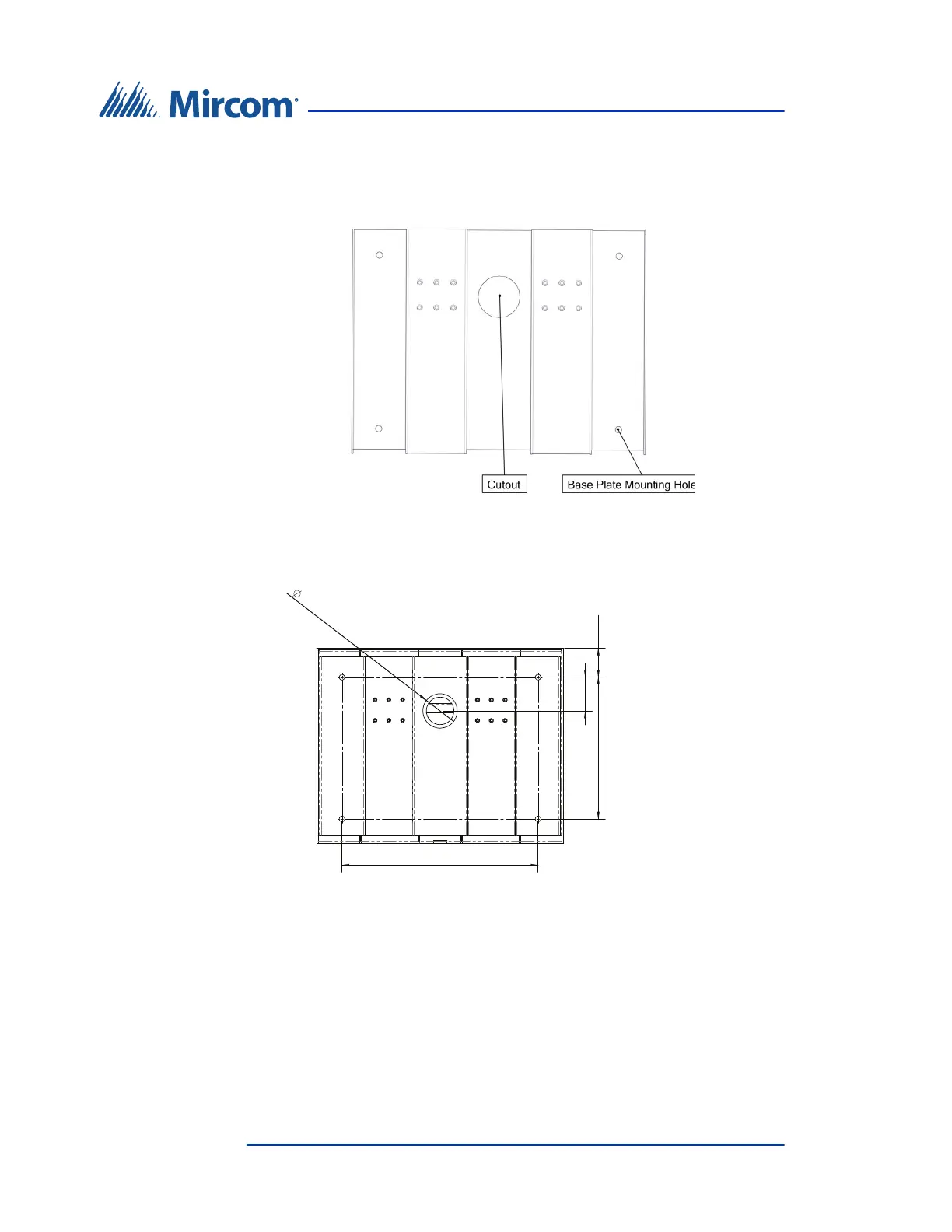
2. Using the base plate as a template, trace an opening on the floor for the
cutout and mark the 4 base plate mounting hole locations as shown in
Figure 22.
Figure 22. Base plate mounting holes
Figure 23 shows the dimensions of the base plate.
Figure 23. Base plate dimensions (inches)
3. Cut an opening in the floor for the electrical and communication cables.
4. Run the wires through the base plate opening.
5. Secure the base plate to the floor using 4 bolts in the base plate mounting
holes shown in Figure 22. The holes are 0.406” in diameter.
10.300
14.244
2.500
2.450
2.107