Installation
132
Mitel 470 as of R4.1
syd-0585/1.2 – R4.1 – 08.2016
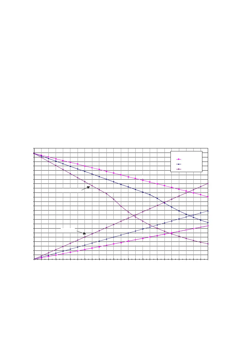
The two diagrams below show the power available on the DSI-AD2 bus in relation to
the line length and the wire diameter. The table can then be used to determine the
number and type of system phones that can be connected to the DSI-AD2 bus under
the given conditions. The power available can be calculated by measuring the loop re-
sistance where the wire diameter is known.
Due to the different hardware versions of the radio units, the power available on the
DSI-AD2 bus is not the same in every case:
Power available A:
• Applies to all the system phones of the MiVoice 5300 series and the Office series.
• Applies to the SB-4+/SB-8 DECT radio units with hardware version "-1".
Fig. 47 Power available A on the DSI-AD2 bus
Power available B:
Applies to the SB-4+/SB-8 DECT radio units with hardware version "-2" and system
phones of the Dialog 4200 series.
6) The value applies to each interface and to radio units with hardware version "-2". The value per interface for
radio units with hardware version "-1" is 150 mW lower.
7) The value applies to phones with hardware version "-2". The value for phones with hardware version "-1" is
60 mW lower.
500
600
700
800
900
1000
1100
1200
1300
1400
1500
1600
1700
1800
1900
2000
2100
2200
2300
2400
2500
2600
2700
2800
2900
3000
0
50
100
150
200
250
300
350
400
450
500
550
600
650
700
750
800
850
900
950
1000
1050
1100
1150
1200
d = 0.6 mm
d = 0.5 mm
d = 0.4 mm
d=0.4mm
500
480
460
440
420
400
380
360
340
320
300
280
260
240
220
200
180
160
140
120
100
80
60
40
20
0
d=0.4mm
d=0.5mm
d=0.6mm
d=0.6mm
d=0.5mm
Pmax [mW]
R [Ohm]
Power available A on the DSI-AD2 bus Pmax [mW]
Loop resistance R [Ohm]
Line length L [m]
d: Wire diameter