FX Series Programmable Controlers Applied Instructions 5
5-11
Controlling interrupt operations:
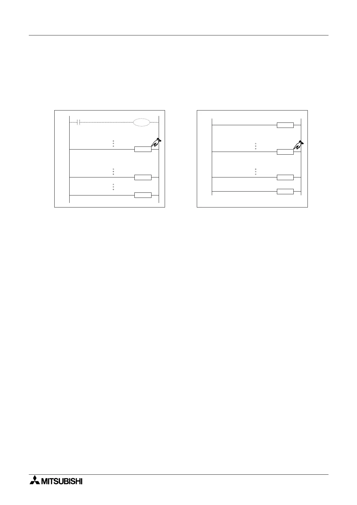
The PLC has a default status of disabling interrupt operation. The EI instruction must be used
to activate the interrupt facilities. All interrupts which physically occur during the program scan
period from the EI instruction until the FEND or DI instructions will have their associated
interrupt routines run. If these interrupts are triggered outside of the enclosed range (EI-FEND
or EI-DI, see diagram below) they will be stored until the EI instruction is processed on the
following scan. At this point the
interrupt routine will be run.
If an individual interrupt is to be disabled its associated special M coil must be driven ON.
While this coil is ON the interrupt routine will not be activated. For details about the disabling M
coils see the PLC device tables in chapter 8.
Nesting interrupts:
Interrupts may be nested for two levels. This means that an interrupt may be interrupted during
its operation. However, to achieve this, the interrupt routine which may be further interrupted
must contain the EI and DI instructions; otherwise as under normal operation, when an
interrupt routine is activated all other interrupts are disabled.
Simultaneously occurring interrupts:
If more than one interrupt occurs sequentially, priority is given to the interrupt occurring first. If
two or more interrupts occur simultaneously, the interrupt routine with the lower pointer number
is given the higher priority.
Using general timers within interrupt routines:
FX PLC’s have a range of special timers which can be used within interrupt routines. For more
information please see page 4-18, Timers Used in Interrupt and ‘CALL’ Subroutines.
Input trigger signals - pulse duration:
Interrupt routines which are triggered directly by interrupt inputs, such as X0 etc., require a
signal duration of approximately 200µsec, i.e. the input pulse width is equal or greater than
200µsec. When this type of interrupt is selected, the hardware input filters are automatically
reset to 50µsec. (under normal operating circumstances the input filters are set to 10msec.).
Pulse catch function:
Direct high speed inputs can be used to ‘catch’ short pulsed signals. When a pulse is received
at an input a corresponding special M coil is set ON. This allows the ‘captured’ pulse to be
used to trigger further actions, even if the original signal is now OFF. FX
1S,FX1N,FX2N and
FX
2NC units require the EI instruction (FNC 04) to activate pulse catch for inputs X0 through
X5, with M8170 to M8175 indicating the caught pulse. Note that, if an input device is being
used for another high speed function, then the pulse catch for that device is disabled.
EI
DI
FEND
I301
IRET
Disabled Interrupts
Enabled Interrupts
routine
Interrupt
EI
FEND
IRET
I101
Disabled Interrupts
Enabled Interrupts
routine
Interrupt
 Loading...


