FX Series Programmable Controlers Applied Instructions 5
5-80
5.6.9 PWM (FNC 58)
Operation:
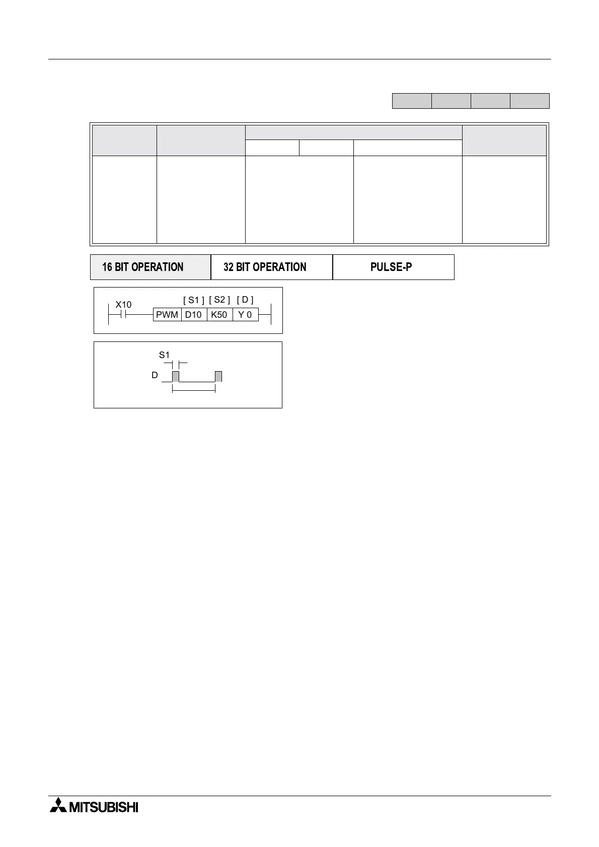
A continuous pulse train is output through device D
when this instruction is driven. The characteristics
of the pulse are defined as:
The distance, in time (msec), between two
identical parts of consecutive pulses (S
2).
And how long, also in time (msec), a single pulse
will be active for (S
1).
Points to note:
a) Because this is a 16 bit instruction, the available time ranges for S
1 and S2 are 1 to 32,767.
b) A calculation of the duty cycle is easily made by dividing S
1 by S2. Hence S1 cannot have a
value greater than S
2 as this would mean the pulse is on for longer than the distance
between two pulses, i.e. a second pulse would start before the first had finished. If this is
programmed an error will occur.
This instruction is used where the length of the pulse is the primary concern.
c) The PWM instruction may only be used once in a users program.
d) Because of the nature of the high speed output, transistor output units should be used with
this instruction. Relay outputs will suffer from a greatly reduced life and will cause false
outputs to occur due to the mechanical ‘bounce’ of the contacts. To ensure a ‘clean’ output
signal when using transistor units, the load current should be 200mA or higher with the
FX2N Series. The load current should be 10 - 100mA with the FX1S/1N Series. It may be
found that ‘pull up’ resistors will be required.
Mnemonic Function
Operands
Program steps
S
1 S2 D
PWM
FNC 58
(
Pulse width
modulation)
Generates a
pulse train with
defined pulse
characteristics
K, H,
KnX, KnY, KnM,
KnS,
T, C, D, V, Z
Note:
S1
S2
Y
Note:
All units: Y000 or Y001
only
)
PWM:
7steps
FX
1S
FX
1N
FX
2N
FX
2NC
PULSE-P
16 BIT OPERATION
32 BIT OPERATION
X10
K50D10 Y 0PWM
[ S1 ]
[ S2 ] [ D ]
D
S1
S2

 Loading...


