FX Series Programmable Controlers Applied Instructions 5
5-104
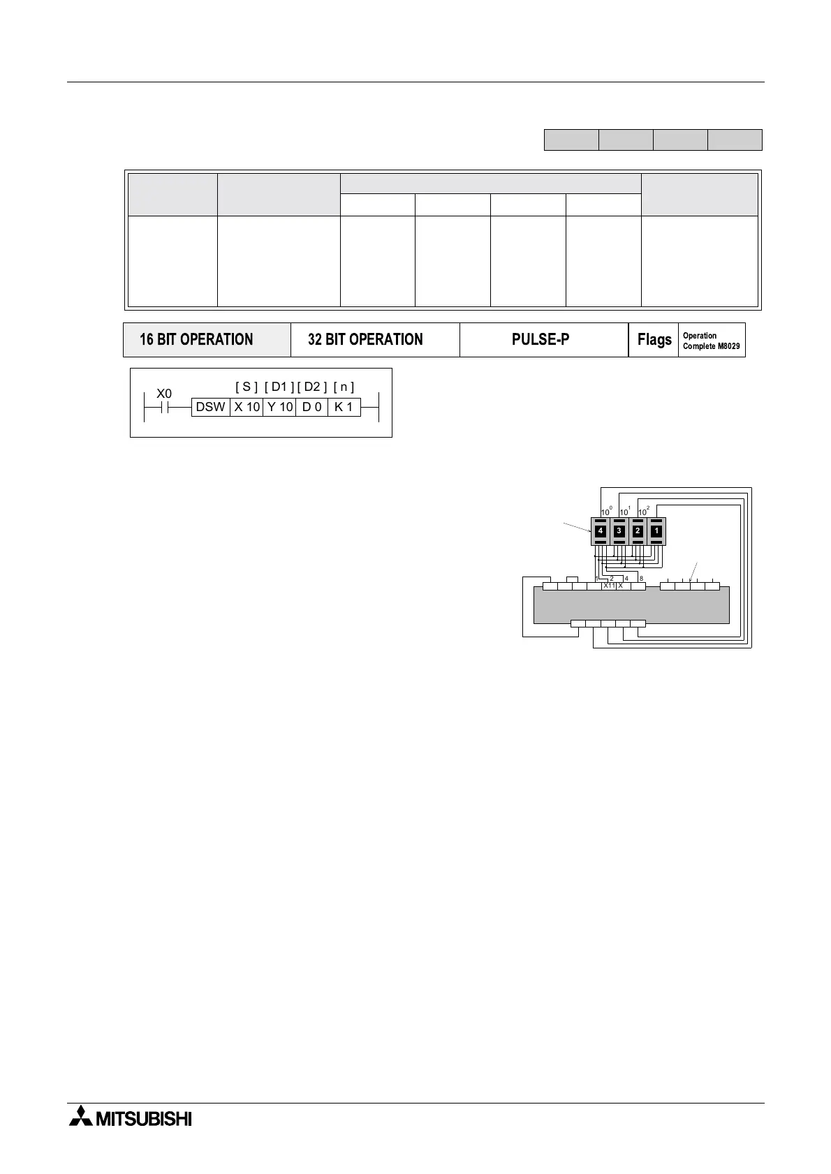
5.8.3 DSW (FNC 72)
Operation:
This instruction multiplexes 4 outputs (D
1) through 1
or 2(n) sets of switches. Each set of switches
consists of 4 thumbwheels providing a single digit
input.
Points to note:
a) When n = 1 only one set of switches are read. The
multiplex is completed by wiring the thumbwheels
in parallel back to 4 consecutive inputs from the
head address specified in operand S. The (4 digit)
data read is stored in data device D
2.
Continued on next page...
Mnemonic Function
Operands
Program steps
SD
1 D2 n
DSW
FNC 72
(Digital
switch)
Multiplexed
reading of n sets
of digital (BCD)
thumbwheels
X
Note:
If n=2 then
8
devices
else 4.
Y
Note:
uses 4
consecutive
devices
T, C, D, V, Z
Note: If
n=2 then 2
devices
else 1.
K, H
)
Note:
n= 1 or 2
DSW:
9steps
FX
1S
FX
1N
FX
2N
FX
2NC
PULSE-P
16 BIT OPERATION
32 BIT OPERATION
Flags
Operation
Complete M8029
X0
Y 10 D 0
[ D2 ]
K 1DSW
[ D1 ]
X 10
[ S ] [ n ]
1248
4 2 1
10 10 10
012
3
X11 X12 X13
24V
0V S/S
X14 X15 X16 X17
Y12 Y13+V Y10 Y11
1248
X10
3
10
Transistor Outputs (source)
BCD digital
switches
(1st set)
2nd
switch
set inputs

 Loading...


