FX Series Programmable Controlers Applied Instructions 5
5-105
b) When n= 2, two sets of switches are read. This configuration requires 8 consecutive inputs
taken from the head address specified in operand S. The data from the first set of switches,
i.e. those using the first 4 inputs, is read into data device D
2. The data from the second set
of switches (again 4 digits) is read into data device D
2+1.
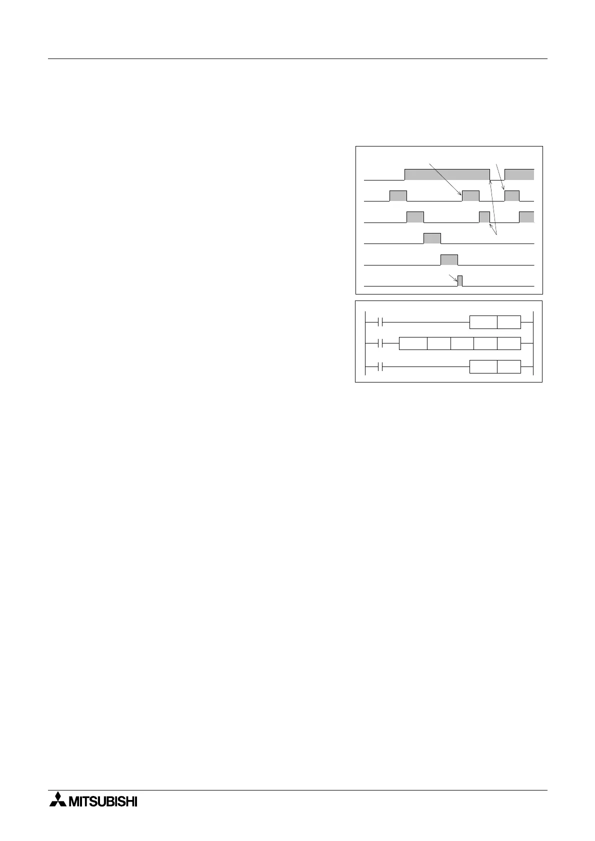
c) The outputs used for multiplexing (D
1)are
cycled for as long as the DSW instruction is
driven. After the completion of one reading, the
execution complete flag M8029 is set. The
number of outputs used does not depend on
thenumberofswitchesn.
d) If the DSW instruction is suspended during mid-
operation, when it is restarted it will start from
the beginning of its cycle and not from its last
status achieved.
e) It is recommended that transistor output units
are used with this instruction. However, if the
program technique at the right is used, relay
output units can be successfully operated as
the outputs will not be continually active.
f) The DSW instruction may be used TWICE on
FX
2N &FX2NC controllers. FX1S &FX1N units
can operate an Unlimited number of DSW
instructions.
X0
Y10
Y11
Y12
Y13
M8029
Start of repetitive operation
Restart
Suspended
operation
Cycle complete
Y 10 D 0 K 1DSW X 10
M0
M8029
X0
RST
M 0
SET
M 0
 Loading...


