FX Series Programmable Controlers Applied Instructions 5
5-175
5.14.1 TCMP (FNC 160)
Contents:
S
1,S2 and S3 represent hours, minutes and
seconds respectively. This time is compared to the
time value in the 3 data devices specified by the
head address S. The result is indicated in the 3 bit
devices specified by the head address D.
The bit devices in D indicate the following:
D
+0 issetON,whenthetimeinSislessthanthetimeinS1,S2 and S3.
D
+1 is set ON, when the time in S is equal to the time in S1,S2 and S3.
D
+2 is set ON, when the time in S is greater than the time in S1,S2 and S3.
Points to note:
a) The status of the destination devices is kept, even if the TCMP instruction is deactivated.
b) The comparison is based on the time value specified in the source devices.
- The valid range of values for S
1 and S+0 is0to23(Hours).
- The valid range of values for S
2 and S+1 is0to59(Minutes).
- The valid range of values for S
3 and S+2 is0to59(Seconds).
c) The current time of the real time clock can be compared by specifying D8015 (Hours),
D8014 (Minutes) and D8013 (Seconds) as the devices for S
1,S2 and S3 respectively.
Mnemonic Function
Operands
Program steps
S
1 S2 S3 SD
TCMP
FNC 160
(Time
Compare)
Compares two
times - results of
<, = and > are
given
K, H,
KnX, KnY, KnM, KnS,
T, C, D,
V, Z
T, C , D Y, M, S TC MP,
TCMPP:
11 steps
Note:
3 consecutive
devices are used.
FX
1S
FX1N FX2N
FX2NC
PULSE-P
16 BIT OPERATION
32 BIT OPERATION
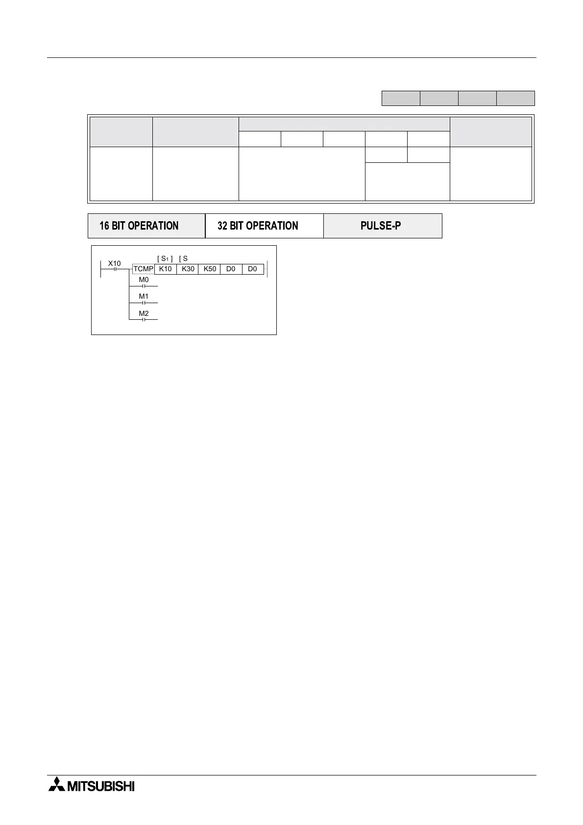
X10
K10 K30
K50
D0
D0TCMP
M0
M1
M2
[ S
1
] [ S
2
]
[ S ][ S
3
] [ D ]
ON when D0,D1,D2 < 10:30:50
ON when D0,D1,D2 = 10:30:50
ON when D0,D1,D2 > 10:30:50
 Loading...


