FX Series Programmable Controlers Applied Instructions 5
5-89
5.7.4 INCD (FNC 63)
Operation:
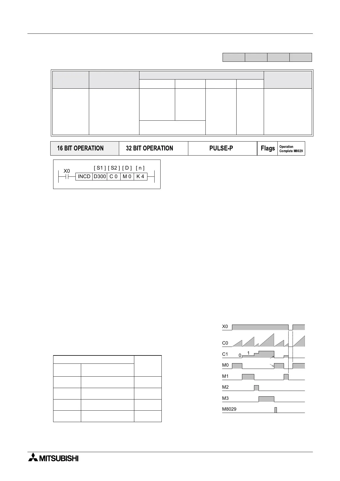
This instruction generates a sequence of
sequential output patterns (there are n number of
addressed outputs) in response to the current
value of a pair of selected counters (S2, S2+1).
Points to note:
a) This instruction uses a ‘data table’ which contains a single list of values which are to be
selected and compared by two consecutive counters (S2and S2+1). The data table is
identified as having a head address S1and consists of n data elements.
b) Counter S2 is programmed in a conventional way. The set value for counter S2 MUST be
greater than any of the values entered into the data table. Counter S2 counts a user event
and compares this to the value of the currently selected data element from the data table.
When the counter and data value are equal, S2 increments the count of counter S2+1and
resets its own current value to ‘0’ (zero).
This new value of counter S2+1selects the new data element from the data table and
counter S2now compares against the new data elements value.
c) The counter S2+1 may have values from 0 to n. Once the nth data element has been
processed, the operation complete flag M8029 is turned ON. This then automatically resets
counter S2+1hence, the cycle starts again with data element S1+0.
d) Values from 0 to 32,767 may be used in the data table.
e) The INCD instruction may only be used ONCE in a
program.
Fromtheexampleinstructionandthedatatable
identified left, the following timing diagram for elements
M0 to M3 can be constructed.
Mnemonic Function
Operands
Program steps
S
1 S2 Dn
INCD
FNC 63
(Incremental
drum
sequencer)
Generates a
single output
sequence in
response to
counter data
KnX, KnY,
KnM, KnS,
(in groups of
8)
T, C, D
C
Uses 2
consecu-
tive
counters
Y, M, S
Note:
n consec-
utive
devices
are used
K,H
)
Note:
n≤ 64
INCD:
9steps
Note: High speed
counters are not allowed
FX
1S
FX
1N
FX
2N
FX
2NC
PULSE-P
16 BIT OPERATION
32 BIT OPERATION
Flags
Operation
Complete M8029
X0
C 0D300 M 0
[ S1 ]
[ S2 ]
[ D ]
K 4
[ n ]
INCD
X0
C0
C1
M0
M1
M2
M3
M8029
0
1
2
3
0
1
20
30
40
10
20
Cycle restarts
D300
Data table
Value of
counter
S2+1
D301
D302
D303
20
30
10
40
0
1
2
3
Data
element
Data value / count value
for counter S2
 Loading...


