FX Series Programmable Controllers STL Programming 3
3-15
3.10 General Precautions When Using
FX-PCS/AT-EE Software
This software has the ability to program in SFC flow diagrams. As part of this ability it can read
and convert existing STL programs back into SFC flows even if they were never originally
programmed using the FX-PCS/AT-EE software. As an aid to allowing this automatic SFC flow
generation the following rules and points should be noted:
1) When an STL flow is started it should be initialized with one of the state devices from the
range S0 to S9.
2) Branch selection or merging should always be written sequentially moving from left to right.
This was demonstrated on page 3-11, i.e. on the selective branch S21 was specified before
S31 which was specified before S41. The merge states were programmed in a similar
manner, S29 proceeded S39 which proceeded S49.
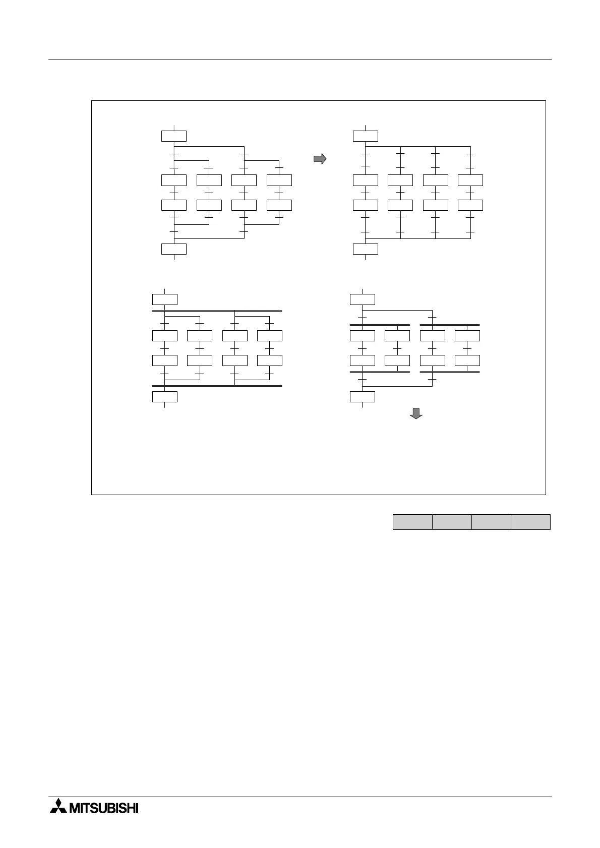
3) The total number of branches which can be programmed with the STL programming mode
are limited to a maximum of 16 circuits for an STL flow. Each branch point is limited to a
maximum of 8 branching flows. This means two branch points both of 8 branch flows would
equal the restriction. These restrictions are to ensure that the user can always view the STL
flow diagram on the computer running the FX-PCS-AT/ EE software and that when it is
needed, the STL program flow can be printed out clearly.
X0
X2
X3
S 21
S 22
S 20
X7
S 29
X1
X5
X6
S 23
S 24
X4
X10
X12
X13
S 25
S 26
X17
X11
X15
X16
S 27
S 28
X14
X2
X3
S 21
S 22
X1
X5
X6
S 23
S 24
X4
X12
X13
S 25
S 26
X11
X15
X16
S 27
S 28
X14
X0 X0 X10 X10
S 20
X7 X7 X17 X17
S 29
X0
S 20
X6
S 29
X1
X7
X2
S 21
S 22
X3
S 23
S 24
X4
S 25
S 26
X5
S 27
S 28
20
0
21
23
1
25
27
S
X
S
S
X
S
S
STL
LD
SET
SET
LD
SET
SET
22SSTL
24
6
29
26
28
7
29
S
X
S
S
S
X
S
STL
LD
SET
STL
STL
LD
SET
Further recommended program changes:
Rewrite as...
Rewrite as...
Program violation!
FX
1S
FX1N FX2N
FX2NC

 Loading...


