Assigning System Devices 9
9-1
9. Assigning System Devices
9.1 Addressing Extension Modules
Most of the FX family of PLC’s have the ability to connect additional discreet I/O and/or special
function modules. To benefit from these additional units the user must address each block
independently.
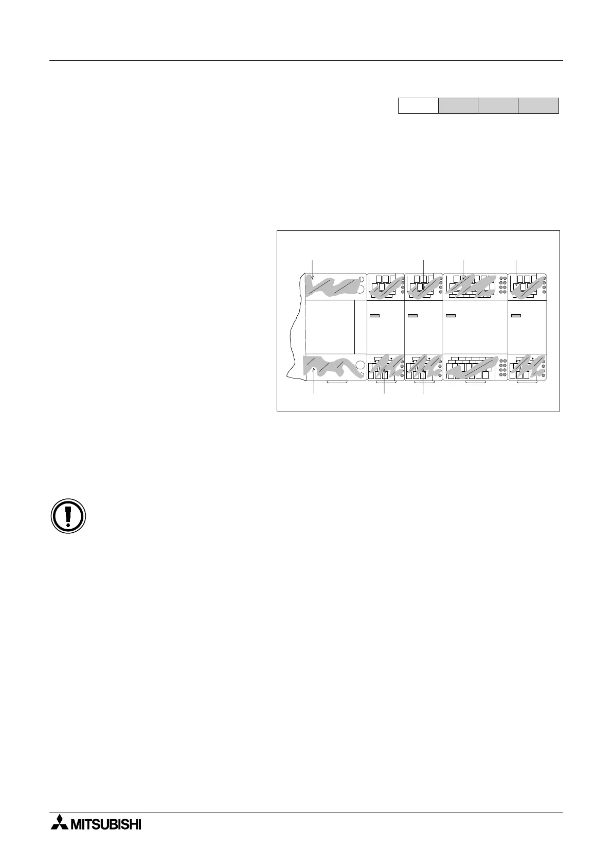
Addressing Additional Discrete I/O
This type of I/O is the standard
input and output modules. As each
extension block or powered
extension unit is added to the
system they assume the next
available addresses. Hence, the
units closest to the base unit will
have the lowest I/O numbers or
addresses. I/O numbers are
always counted in octal. This
means from 0 to 7 and 10 to 17
etc. Within a users program the
additional addresses are used as
normal. Discreet I/O can be added
at the users discretion as long as
the rules of system configuration for each PLC type are obeyed. This information can be found
in the appropriate hardware manual.
For easy use and identification, each additional I/O unit should be labeled with the appropriate
I/O numbers using the provided number labels.
Caution when using an FX system with FX-8ER, FX-24MR units
• When an FX-8ER or an FX-24MR are used an additional 8 points (as 4 inputs, 4 outputs)
of I/O must be allowed for. This is because both units split blocks of 8 inputs and 8
outputs to obtain a physical 4 input/ 4 output configuration. Hence, an FX-8ER unit
actually occupies 8 input points and 8 output points even though there are only 4
physical inputs and 4 physical outputs.
Addressing Special Function Blocks
Special function blocks are allocated a logical ‘station/block number’ from 0 to 7. This is used
by the FROM/TO instructions to directly access each independent special function module.
The lower the ‘station/block number’ is, the closer to the base unit it can be found. Special
function blocks can be added at the users discretion but the rules of configuration for each type
of PLC must be obeyed at all times. The configuration notes can be found in the appropriate
hardware manual for each programmable controller.
FX
1S
FX
1N
FX
2N
FX
2NC
POWER
FX-16EX
POWER
FX-8EX
POWER
FX-8EYT
POWER
FX-8EYR
FX-48MR
X0-27
X30-X37 X40-X57 X60-X67
Y0-Y27
Y30-Y37 Y40-Y47
FX Series Programmable Controllers

 Loading...


