FX Series Programmable Controlers Applied Instructions 5
5-114
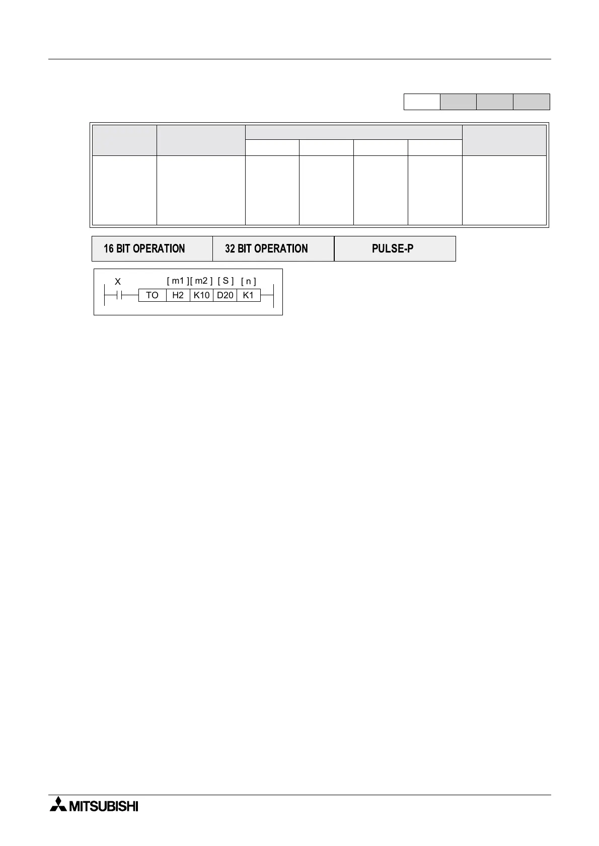
5.8.10 TO (FNC 79)
Operation:
The TO instruction writes n words of data to the
head buffer memory address m
2 of the special
function block with the logical block position
specified in m
1. The written data is taken from the
PLC’s head address S for n word devices.
Points to note:
All points are the same as the FROM instruction (see previous page) except point c) which is
replaced by the following:
a) The source head address for the data written TO the special function block is specified
under the S operand.
Mnemonic Function
Operands
Program steps
m
1 m2 Sn
TO
FNC 79
(TO)
Writes data to the
buffer memories
of attached
special function
blocks
K, H
)
Note:
m
1=0to7
K, H
)
Note:
m
2 =0to
32767
K,H, KnX,
KnY, KnM,
KnS, T, C,
D, V, Z
K, H
)
Note:
16 bit op:
n=1to32
32 bit op:
n=1to16
TO, TOP:
9steps
DTO, DTOP:
17 steps
FX
1S
FX
1N
FX
2N
FX
2NC
PULSE-P
16 BIT OPERATION
32 BIT OPERATION
TO H2 D20K10 K1
[ m1 ]
[ m2 ]
[ S ]
[ n ]
X0

 Loading...


