FX Series Programmable Controllers STL Programming 3
3-4
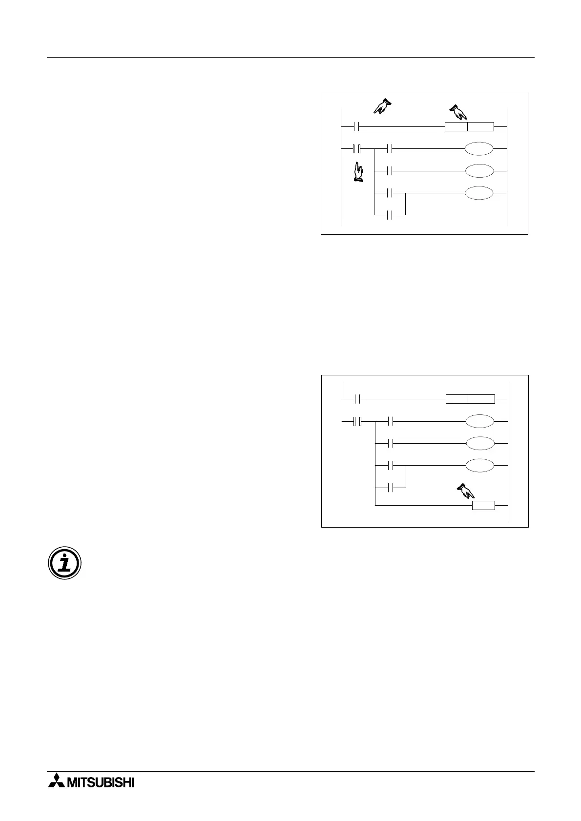
Initial Steps
For an STL program which is to be activated
on the initial power up of the PLC, a trigger
similar to that shown opposite could be used,
i.e. using M8002 to drive the setting of the
initial state.
The STL step started in this manner is often
referred to as the initial step. Similarly, the
step activated first for any STL sequence is
also called the initial step.
3.3.3 Terminating an STL Program
Once an STL program has been started the programmable controllers CPU will process all fol-
lowing instructions as being part of that STL program. This means that when a second pro-
gram scan is started the normal instructions at the beginning of the program are considered to
be within the STL program. This is obviously incorrect and the CPU will proceed to identify a
programming error and disable the programmable controllers operation.
This scenario may seem a little strange but it does make sense when it is considered that the
STL program must return control to the ladder program after STL operation is complete. This
means the last step in an STL program needs to be identified in some way.
Returning to Standard Ladder
This is achieved by placing a RET or RETurn
instruction as the last instruction in the last
STL step of an STL program block.
This instruction then returns programming con-
trol to the ladder sequence.
STL
S005
M8002
SET S005
X001
X000
X012
X013
Y000
Y011
Y014
STL
S005
M8002
SET S005
X001
X000
X012
X013
Y000
Y011
Y014
RET
Note: The RET instruction can be used to separate STL programs into sections, with stan-
dard ladder between each STL program. For display of STL in SFC style format the RET
instruction is used to indicate the end of a complete STL program.
 Loading...


