FX Series Programmable Controllers Points Of Technique 10
10-6
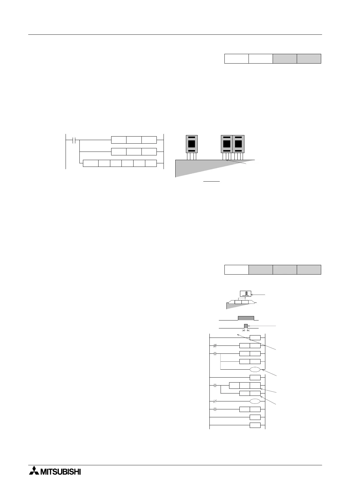
10.8 Reading And Manipulating Thumbwheel Data
Data can be easily read into a programmable controller through the use of the BIN instruction.
When data is read from multiple sources the data is often stored at different locations. It may
be required that certain data values are combined or mixed to produce a new value.
Alternatively, a certain data digit may need to be parsed from a larger data word. This kind of
data handling and manipulation can be carried out by using the SMOV instruction. The
example below shows how two data values (a single digit and a double digit number) are
combined to make a final data value.
Explanation:
The two BIN instructions each read in one of the data values. The first value, the single digit
stored in D1, is combined with the second data value D2 (currently containing 2 digits). This is
performed by the SMOV instruction. The result is that the contents of D1 is written to the third
digit of the contents of D2. The result is then stored back into register D2.
10.9 Measuring a High Speed Pulse Input
10.9.1 A 1 msec timer pulse measurement
Some times due to system requirements or even
as a result of maintenance activities it is
necessary to 'find out' how long certain input
pulses are lasting for. The following program
utilizes two interrupt routines to capture a pulse
width and measure it with a 1 msec timer. The
timer used in the example is one of the FX
timers. However, T63 on the FX1N would be
used for a similar situation on that PLC.
Explanation:
The 1 msec timer T246 is driven when interrupt
I001 is activated. When the input to X1 is
removed the current value of the timer T246 is
moved to data register D0 by interrupt program
I100. The operation complete flag M0 is then set
ON.
Note: X10 acts as an enable/disable flag.
FX1S
FX
1N
FX
2N
FX
2NC
M8000
SMOV D1 K1
BIN
K1
K2X20 D2
BIN K1X0 D1
D2 K3
657
X0 to X3 X20 to X27
D2 = 65
D1=7
D1- D2 D2=765
10
0
1
0
Digit
10
10
Digit
SMOV
FX prpgrammable
controller
FX
1S
FX
1N
FX
2N
FX
2NC
X 10
S (X0, X1)
X 0 X 1
FEND
M8000
RST T246
X10
RST M 0
RST D 0
IRET
X10
D 0MOV T246
SET M 0
M0
K1
RST T246
M8000
IRET
END
I001
I100
T246
K32767
T246
General wiring-pluse
to be measured is
connected to both X0
and X1
Pulse to be
measured
EI instruction
MUST be
included in main
program
Pulse has been
measured
1 msec timer-
FX
0N
use T63
Measured time
stored inD0

 Loading...


