FX Series Programmable Controlers Applied Instructions 5
5-88
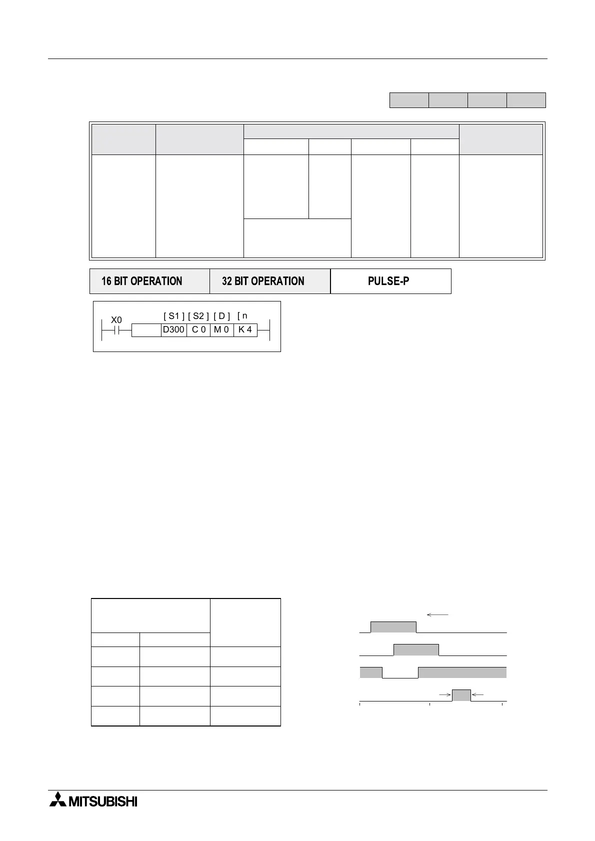
5.7.3 ABSD (FNC 62)
Operation:
This instruction generates a variety of output
patterns (there are n number of addressed
outputs) in response to the current value of a
selected counter, S2.
Points to note:
a) The current value of the selected counter (S2) is compared against a user defined data
table. This data table has a head address identified by operand S1. S1should always have
an even device number.
b) For each destination bit (D) there are two consecutive values stored in the data table. The
first allocated value represents the event number when the destination device (D) will be
turned ON. The second identifies the reset event. The data table values are allocated as a
consecutive pair for each sequential element between D and D+n.
c) The data table has a length equal to 2 × n data entries. Depending on the format of the data
table,asingleentrycanbeonedatawordsuchasD300oragroupof16bitdevicese.g.
K4X000.
d) Values from 0 to 32,767 may be used in the data table.
e) The ABSD instruction may only be used ONCE.
From the example instruction and the data table below, the following timing diagram for
elements M0 to M3 can be constructed.
Mnemonic Function
Operands
Program steps
S
1 S2 Dn
ABSD
FNC 62
(Absolute
drum
sequencer)
Generates
multiple output
patterns in
response to
counter data
KnX, KnY,
KnM, KnS,
(in groups
of 8)
T, C, D
CY,M,S
Note:
n
consecutive
devices are
used
K,H
)
Note:
n≤ 64
ABSD:
9steps
DABSD:
17 steps.
see f).
Note: High speed
counters are not
allowed
FX
1S
FX
1N
FX
2N
FX
2NC
PULSE-P
16 BIT OPERATION
32 BIT OPERATION
X0
C 0D300 M 0
[ S1 ] [ S2 ] [ D ]
K 4
[ n ]
ABSD
D300 - 40
When counter S2 equals the
value below, the destination
device D is
Assigned
destination
device D
D302 - 100
D304 - 160
D306 - 240
D301 - 140
D303 - 200
D305 - 60
D307 - 280
M0
M1
M2
M3
turned ON turned OFF
M 0
M 1
M 2
M 3
40 140
100 200
60 160
240 280
0 180 360
Count value
ON
OFF

 Loading...


