FX Series Programmable Controlers Applied Instructions 5
5-95
5.7.9 ROTC (FNC 68)
Operation:
The ROTC instruction is used to aid the tracking
and positional movement of the rotary table as it
moves to a specified destination.
Points to note:
a) This instruction has many automatically de-
fined devices. These are listed on the right of
this page.
b) The ROTC instruction may only be used
ONCE.
c) The ROTC instruction uses a built in 2-phase
counter to detect both movement direction
and distance travelled. Devices D+0and D+1
are used to input the phase pulses, while
device D+2is used to input the ‘zero position’
on the rotary table. These devices should be
programmed as shown in the example below
(where the physical termination takes place
at the associated X inputs).
The movement direction is found by checking
the relationship of the two phases of the 2
phase counter, e.g.
Mnemonic Function
Operands
Program steps
Sm
1 m2 D
ROTC
FNC 68
(Rotary
table
control)
Controls a rotary
tables movement
is response to a
requested
destination/
position
D
Note:
uses 3
consecu-
tive
devices
S+1≤ m1
K, H
)
Note:
m1= 2 to
32,767
K, H
)
Note:
m2= 0 to
32,767
Y, M, S
Note:
uses 8
consecu-
tive
devices
ROTC:
9steps
m1≥ m2
FX
1S
FX
1N
FX
2N
FX
2NC
PULSE-P
16 BIT OPERATION
32 BIT OPERATION
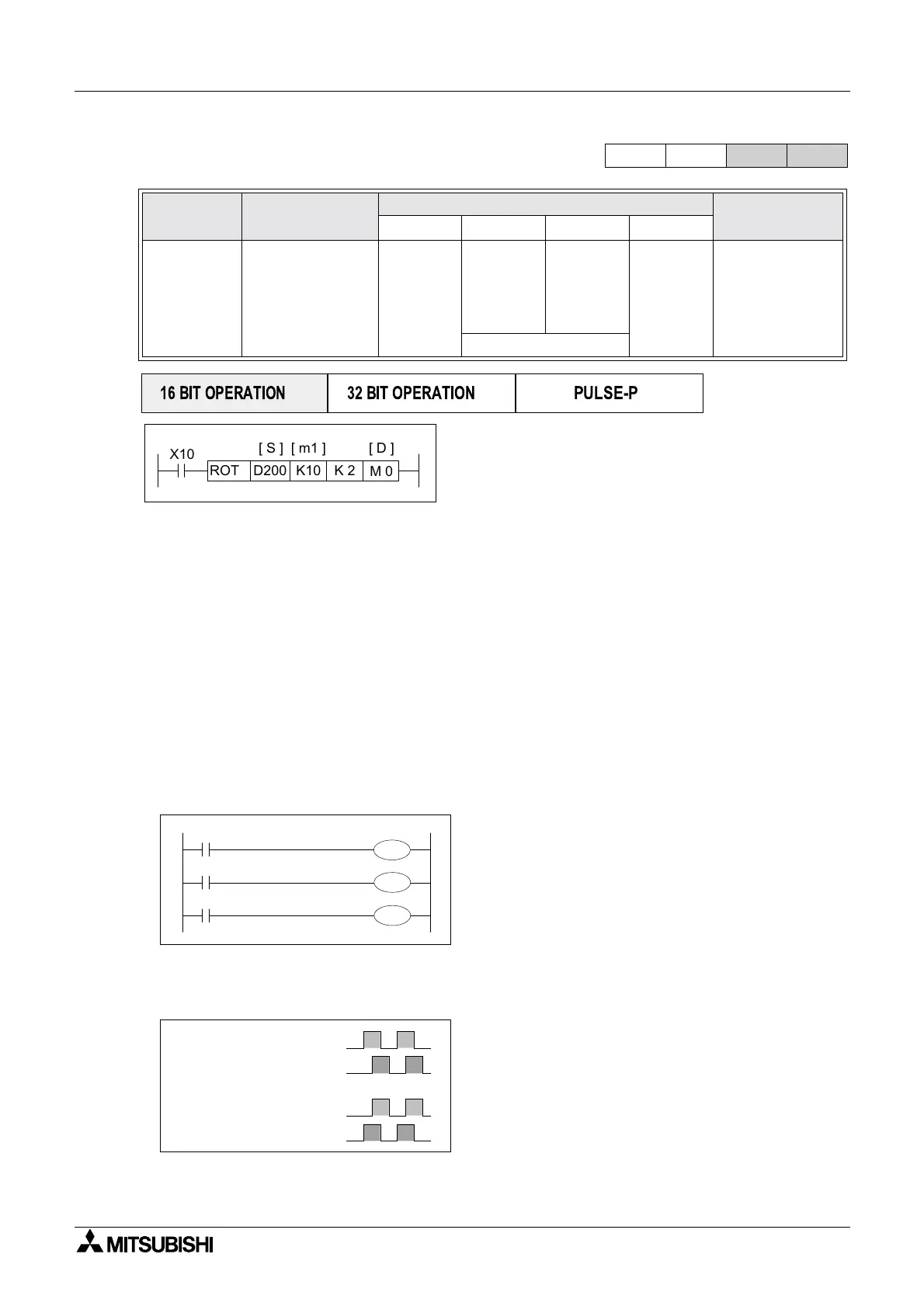
X10
K10D200 K 2
[ S ] [ m1 ] [ D ]
M 0
ROTC
[ m2 ]
Assigned devices
Indirect user selected devices:
D
+0
A-phase counter signal - input
D
+1
B-phase counter signal - input
D
+2
Zero point detection - input
D
+3
High speed forward - output
D
+4
Low speed forward - output
D
+5
Stop - output
D
+6
Low speed reverse - output
D
+7
High speed reverse - output
Rotary table constants:
m
1
Number of encoder pulses per
table revolution
m
2
Distance to be travelled at low
speed (in encoder pulses)
Operation variables:
S
+0
Current position at the ‘zero point’
READ ONLY
S
+1
Destination position (selected
station to be moved to) relative to
the ‘zero point’ - User defined
S
+2
Start position (selected station to
be moved) relative to the ‘zero
point’ -User defined
X1
X2
X0
M 0
M 1
M 2
A-phase
B-phase
A-phase
B-phase
A
phase leads
B
phase
B
phase leads
A
phase

 Loading...


