FX Series Programmable Controlers Applied Instructions 5
5-170
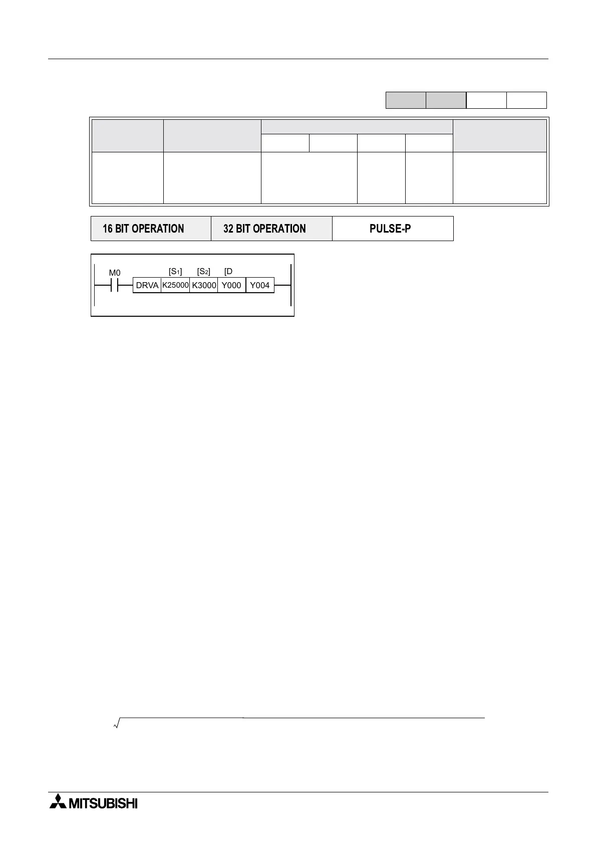
5.13.10 DRVA(FNC 159)
Operation:
This instruction is for single speed positioning
using a zero home point and absolute
measurements.
[S
1
] is the Number of Pulses, [S
2
] is the Output
Frequency, [D
1
] is the Pulse Output Designations, and [D
2
] is the Rotation Direction Signal.
Points to note:
a)The target position for absolute positioning [S
1
] can be: 16-bit -32,768 to 32,767 pulses or
32-bit -999,999 to 999,999 pulses.
b)Users may use output pulse frequencies [S
2
], 16-bit 10 to 32,767Hz or 32-bit 10 to 100kHz.
c)Only Y000 or Y001 can be used for the pulse output [D
1
].
Because of the nature of the high speed output, transistor type output units should be used
with this instruction. Relay type outputs will suffer a greatly reduced life, and will cause false
outputs to occur.
To ensure a ‘clean’ output signal when using transistor type units, the load current should be
200mA or higher with the FX2N Series. The load current should be 10 - 100mA with the FX1S/
1N Series. It may be necessary to use ‘pull up’ resistors.
d)Rotation direction signal output [D
2
] operated as follows: if [D
2
] = OFF, rotation = negative, if
[D
2
] = ON, rotation = positive.
e)If the contents of an operand are changed while the instruction is executed, it is not reflected
on the operation. The new contents become effective when the instruction is next driven.
f)If the instruction drive contact turns off while the instruction is being executed, the machine
decelerates and stops. At this time the execution complete flag M8029 does not turn ON.
g)Once the instruction drive contact is off, re-drive of the instruction is not possible while the
pulse output flag (Y000 : [M8147], Y001 : [M8148]) is ON.
h)For operation in the absolute drive method, the travel distance from the zero point is
specified.
i)The minimum value of output pulse frequency which can be actually used is determined by
the following equation
Mnemonic Function
Operands
Program steps
S
1
S
2
D
1
D
2
DRVA
FNC 159
Drive to
absolute
Absolute
positioning
K,H,
KnX,KnY,
KnM,KnS
T,C,D,V,Z
Y
Note:
Y000 or
Y001 only
Y,M ,S DR VA
9steps
DDRVA
17 steps
FX
1S
FX
1N
FX
2N
FX
2NC
PULSE-P
16 BIT OPERATION
32 BIT OPERATION
DRVA
K25000
K3000 Y004
[S
2][S1]
M0
Y000
[D
1]
[D
2]
MaxSpeed D8147 D8146[,]Hz 2( Acceleration\Deceleration D8148[]ms(× 1000))÷÷

 Loading...


