FX Series Programmable Controlers Applied Instructions 5
5-159
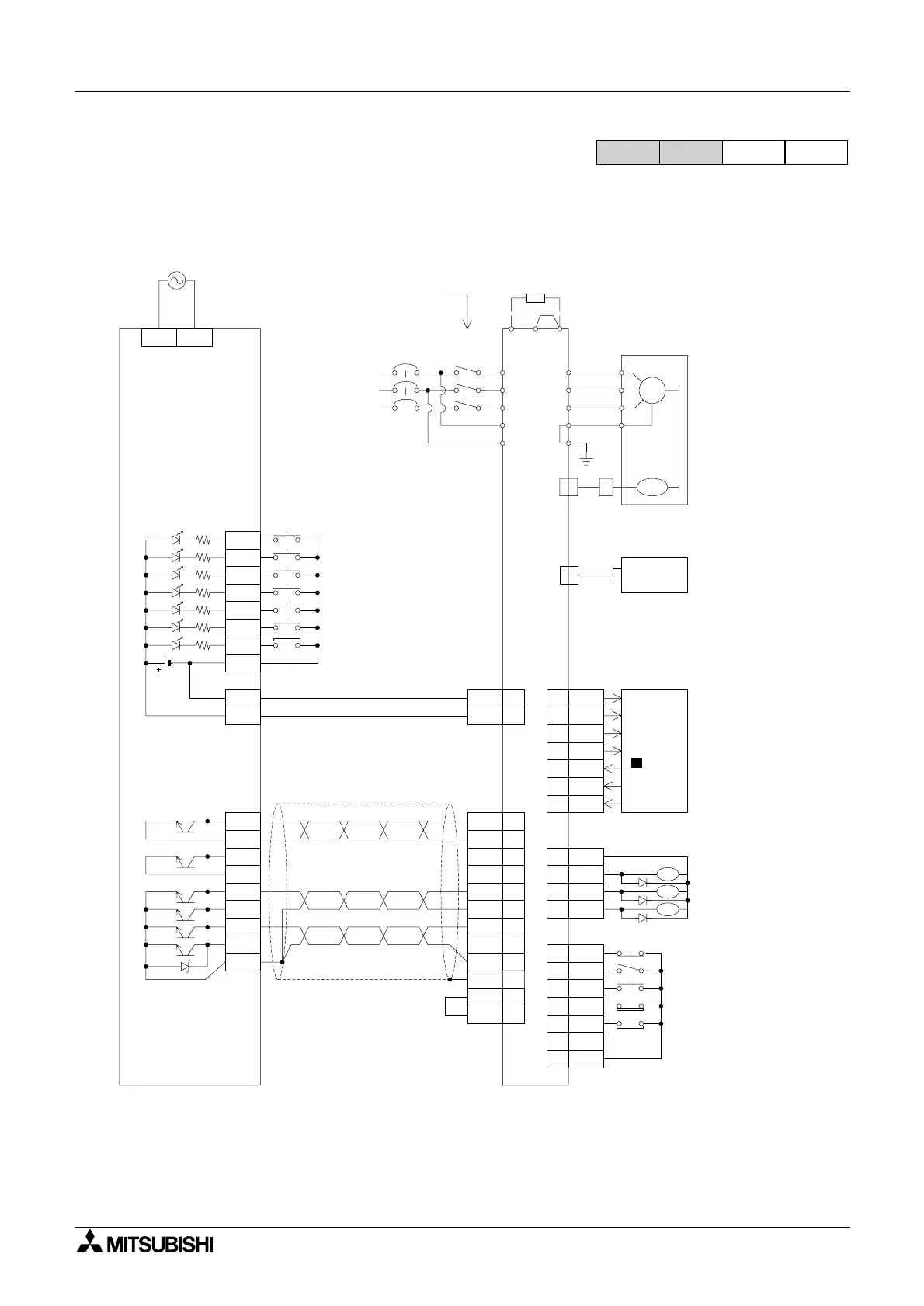
5.13.4 Servo Wiring Example
Example of connection to a Mitsubishi MR-J2-*A servo.
Note. The PLC required for this connection is a SINK Transistor output type.
*1 Connect to programmable controller when absolute position detection is required.
*2 Ports CN1A, CN1B, CN2 & CN3 are the same shape. Do not confuse them.
*3 Connect a limit switch to the servo amplifier.
*4 ONLY use a transistor output type PLC.
FX1S
FX
1N
FX
2N
FX
2NC
Stop
10
13
X000
X001
X002
X003
X004
X005
X006
COM
COM
24+
Y000
COM0
Y001
COM1
Y002
Y003
Y004
Y005
COM2
Return to zero point
Jog (+)
Jog (-)
Positioning in normal rotation
Positioning in reverse rotation
Near point signal (DOG)
L N
85V AC to 264V AC
CDP
MCNFB
200V AC to
230V AC
Construct a sequence in
which MC i s set to OFF by
alarm or emergency stop.
Regenerative
option
SG
COM
PP
3
10
SG
CR
8
10
SG
NP
2
SG
10
COM
9
OPC
11
4
19
ZSP
TLC
6
10
SG
SON
5
8
ABSM
ABSR
9
DO1
Refer to
FNC 155
( ABS).
Personal
computer
L1
L2
L3
L11
L21
PE
PE
U
V
W
Optional
cable
Optional
cable
PG
SM
U
V
W
E
Servo motor
HC-MF/HA-FF
*2
CN2
*2
CN3
CN1B
CN1B
*2
13
19
ZSP
TLC
6
18
ALM
COM
15
5
SON
RES
14
16
LSP
LSN
17
SG
20
EMG
CN1B
Zero speed *1
Servo ON *1
Reset
Normal rotation limit
Reverserotation limit
*3
Torque being limited *1
Failure
CN1A
Programmable controller FX
1S
-30MT Servo amplifier MR-J2-
¨
A
24V
*4
Normal/reverse sign
Clear
Pulsetrain
External emergency stop
CN1B
SD
D

 Loading...


