FX Series Programmable Controllers Points Of Technique 10
10-15
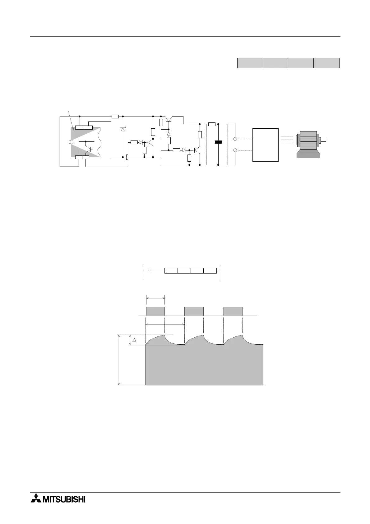
10.13 Using The PWM Instruction For Motor Control
The PWM instruction may be used directly with an inverter to drive a motor. If this configuration
is used the following ripple circuit will be required between the PLC’s PWM output and the
inverters input terminals.
Key to component values:
R1 - 510 Ω (1/2 W) R2 - 3.3kΩ (1/2 W)
R3 to R8 - 1kΩ (1/4 W) R9 - 22 Ω (1/4 W)
R10 - variable dependent on configuration. In this example 1kΩ (1 W)
C1 - 470 µF
Note: the values of R10 and C1 are dependent on the system configuration.
Establishing system parameters and values
It is assumed that the input impedance of the inverter is of a high order. Having established
this, the values of C1 and R10 are calculated to give τ a time result (in msec) approximately 10
times bigger than the value used for T
0 in the PWM instruction:
τ =R10(kΩ) ÅLC1(µF)
During this calculation the value of R10 must be vastly greater than the value of R9. In the
example, R9 is equal to 22Ω, where as R10 is equal to 1kΩ. This proportion is approximately
1:50 in favor of R10.
FX
1S
FX
1N
FX
2N
FX
2NC
Y0+V0
24V 0V
+
E
e
R1
R2
R3 R7
R10
R
4
R
5
R
6
R
9
R
8
Inverter
C1
5V
12V
Programmable
controller
Motor
Circuit configuration for a PLC with source outputs
e
e
m
Y000
t
T
0
PWM D10 K50 Y000
X10
tT0

 Loading...


