FX Series Programmable Controlers Applied Instructions 5
5-188
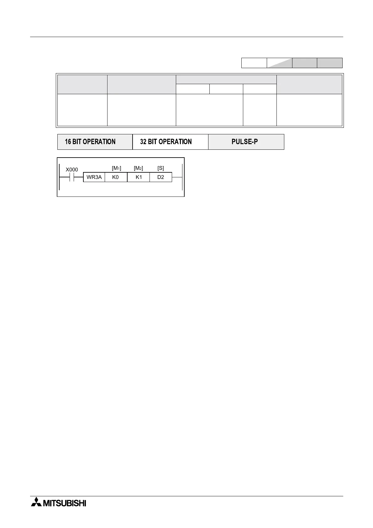
5.15.4 WR3A (FNC 177)
Operation:
This instruction writes data to the FX
0N-3A or FX2N-2DA
analog block.
[M
1
] = Special block number, K0 to K7
[M
2
] = Analog output channel number, K1/K21 or K22
[S] = Write data
Points to note:
Adjustment of the FX
0N-3A or FX2N-2DA analog block characteristics should be completed in advance of
using this instruction. For guidance please see the relevant manual.
For the FX
0N-3A, K1 = Channel 1 (only 1 output channel available) S = 0~255(8 bit)
For the FX
2N-2DA, K21 = Channel 1, K22 = Channel 2 S = 0~4095(12bit)
FX
1N series can only communicate with the FX0N-3A
Mnemonic Function
Operands
Program steps
M1 M2 S
WR3A
FNC 177
Write to Analog
block
Write data to analog
block FX
0N-3A, FX2N-
2AD, FX
2N-2DA
K,H.
KnX, KnY,KnM,KnS,
T,C,D,V,Z
KnY,
KnM,KnS
T.C,D,V,Z
WR3A
7steps
FX
1S
FX
1N
FX
2N
FX
2NC
PULSE-P
16 BIT OPERATION
32 BIT OPERATION
WR3A K0 K1 D2
[M
1] [S][M2]
X000

 Loading...


