FX Series Programmable Controlers Applied Instructions 5
5-30
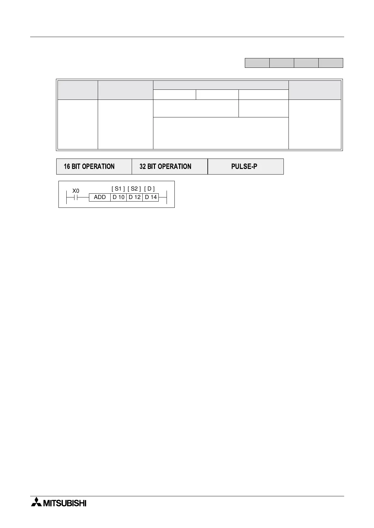
5.3.1 ADD (FNC 20)
Operation: (Applicable to all units)
The data contained within the source devices
(S
1,S2) is combined and the total is stored at the
specified destination device (D).
Points to note:
a) All calculations are algebraically processed, i.e. 5 + (-8)= -3.
b) The same device may be used as a source (S
1 or S2) and as the destination (D). If this is
the case then the ADD instruction would actually operate continuously. This means on
every scan the instruction would add the result of the last scan to the second source device.
To prevent this from happening the pulse modifier should be used or an interlock should be
programmed.
c) If the result of a calculation is “0" then a special auxiliary flag, M8020 is set ON.
d) If the result of an operation exceeds 32,767 (16 bit limit) or 2,147,483,647 (32 bit limit) the
carry flag, M8022 is set ON. If the result of an operation exceeds -32,768 or -2,147,483,648
the borrow flag, M8021 is set ON. When a result exceeds either of the number limits, the
appropriate flag is set ON (M8021 or M8022) and a portion of the carry/borrow is stored in
the destination device. The mathematical sign of this stored data is reflective of the number
limit which has been exceeded, i.e. when -32,768 is exceeded negative numbers are stored
in the destination device but if 32,767 was exceeded positive numbers would be stored at
D.
e) If the destination location is smaller than the obtained result, then only the portion of the
result which directly maps to the destination area will be written, i.e if 25 (decimal) was the
result, and it was to be stored at K1Y4 then only Y4 and Y7 would be active. In binary terms
this is equivalent to a decimal value of 9 a long way short of the real result of 25!
Mnemonic Function
Operands
Program steps
S1 S2 D
ADD
FNC 20
(
Addition)
The value of the
two source
devices is added
and the result
stored in the desti-
nation device
K, H, KnX, KnY, KnM, KnS,
T, C, D, V, Z
KnY, KnM, KnS,
T, C, D, V, Z
ADD, ADDP:
7steps
DADD,
DADDP:
13 steps
When using M8023 to add floating point data,
only double word (32 bit) data registers (D) or
constants (K/H) may be used. See page 4-46
for more details regarding floating point format.
FX
1S
FX
1N
FX
2N
FX
2NC
PULSE-P
16 BIT OPERATION
32 BIT OPERATION
X0
ADD D 10 D 12
[ S1 ] [ D ]
D 14
[ S2 ]

 Loading...


