FX Series Programmable Controlers Applied Instructions 5
5-167
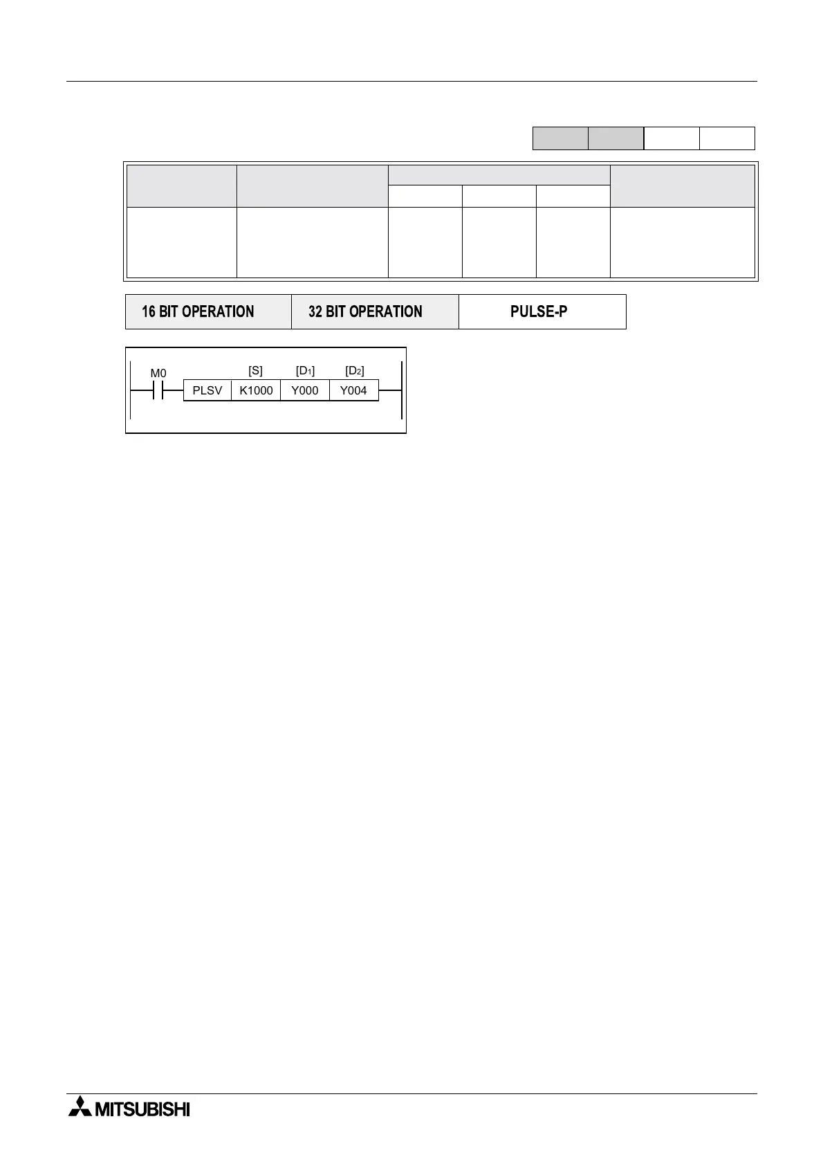
5.13.8 PLSV(FNC157)
Operation:
This is a variable speed output pulse instruction,
with a rotation direction output.
[S] is the Pulse Frequency, [D
1
] is the Pulse Output
Designation, and [D
2
] is the Rotation Direction
Signal.
Points to note:
a)Users may use output pulse frequencies [S
1
] of, 16-bit 10 to 32,767Hz or 32-bit 10 to
100kHz.
b)Only Y000 or Y001 can be used for the pulse output [D
1
].
Because of the nature of the high speed output, transistor type output units should be used
with this instruction. Relay type outputs will suffer a greatly reduced life, and will cause false
outputs to occur.
To ensure a ‘clean’ output signal when using transistor type units, the load current should be
200mA or higher with the FX2N Series. The load current should be 10 - 100mA with the FX1S/
1N Series. It may be necessary to use ‘pull up’ resistors.
c)Rotation direction signal output [D2} operated as follows: if [D
2
] = OFF, rotation = negative, if
[D
2
] = ON, rotation = positive.
d)The pulse frequency [S] can be changed even when pulses are being output.
e)Acceleration/deceleration are not performed at start/stop. If cushion start/stop is required,
increase or decrease the output pulse frequency [S] using the FNC67 RAMP instruction.
f)If the instruction drive contact turns off while pulses are output, the machine stops without
deceleration
g)Once the instruction drive contact is off, re-drive of the instruction is not possible while the
pulse output flag (Y000 : [M8147] Y001 : [M8148]) is ON.
h)The normal or reverse direction is specified by the positive or negative sign of the output
pulse frequency [S]
i)Related device numbers.
D8141 (upper digit) & D8140 (lower digit) : Current value register of Y000 (32-bit)
D8143 (upper digit) & D8142 (lower digit) : Current value register of Y001 (32-bit)
M8145 : Y000 pulse output stop (immediate)
M8146 : Y001 pulse output stop (immediate)
M8147 : Y000 pulse output monitor (BUS/READY)
M8148 : Y001 pulse output monitor (BUS/READY)
• Attention should be paid to the instruction drive timing.
Mnemonic Function
Operands
Program steps
SD1D2
PLSV
FNC 157
Pulse V
Variable speed
pulse output
K,H,
KnX,KnY,
KnM,KnS
T,C,D,V,Z
Y
Note:
Y000 or
Y001 only
Y, M , S P L S V
9steps
DPLSV
17 steps
FX
1S
FX
1N
FX
2N
FX
2NC
PULSE-P
16 BIT OPERATION
32 BIT OPERATION
PLSV K1000 Y000 Y004
[S] [D
2][D1]
M0

 Loading...


