FX Series Programmable Controlers Applied Instructions 5
5-108
d) If the SEGL instruction is suspended during mid-operation, when it is restarted it will start
from the beginning of its cycle and not from its last status achieved.
e) The SEGL instruction may be used TWICE on FX
2N &FX2NC controllers. FX1S &FX1N units
can operate an Unlimited number of SEGL instructions.
Selecting the correct value for operand n
The selection of parameter n depends on 4 factors;
1) The logic type used for the PLC output
2) The logic type used for the seven segment data lines
3) The logic type used for the seven segment strobe signal
There are two types of logic system available, positive logic and negative logic. Depending on
the type of system, i.e. which elements have positive or negative logic the value of n can be
selected from the table below with the final reference to the number of sets of seven segment
displays being used:
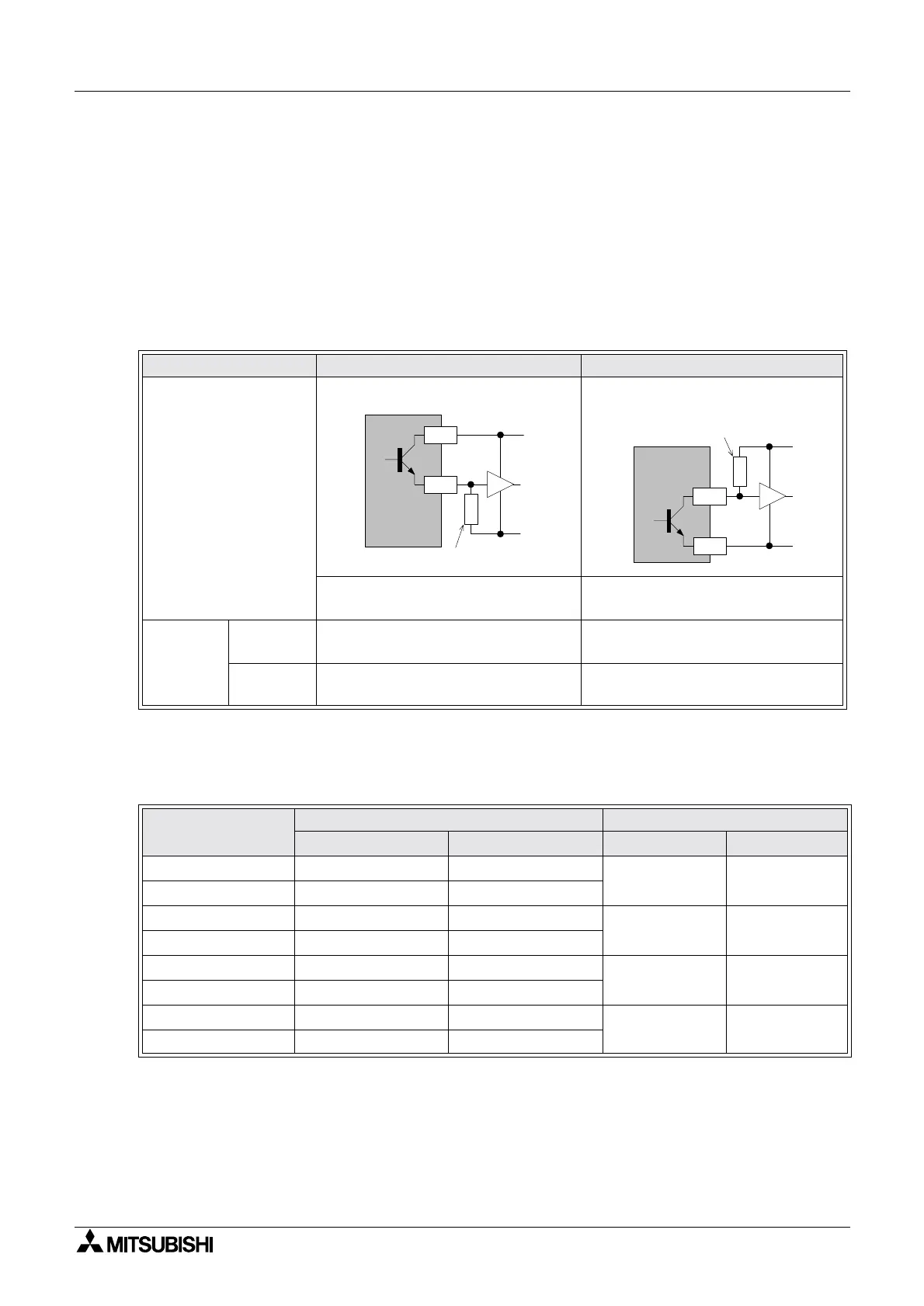
Device considered Positive logic Negative logic
PLC Logic
With a source output, when the
output is HIGH the internal logic is ‘1’
With a sink output, when the output
is LOW the internal logic is ‘1’
Seven
segment
Display
logic
Strobe
signal logic
Data is latched and held when this
signal is HIGH, i.e. its logic is ‘1’
Data is latched and held when this
signal is LOW, i.e. its logic is ‘1’
Data
signal logic
Active data lines are held HIGH,
i.e. they have a logic value of ‘1’
Active data lines are held LOW, i.e.
they have a logic value of ‘1’
PLC Logic
Seven segment display logic n
Data Logic Strobe logic 1displayset 2 display sets
Positive
(Source) Positive (High) Positive (High)
04
Negative
(Sink) Negative (Low) Negative (Low)
Positive (Source) Positive (High) Negative (Low)
15
Negative
(Sink) Negative (Low) Positive (High)
Positive (Source) Positive (High) Negative (Low)
26
Negative
(Sink) Negative (Low) Positive (High)
Positive (Source) Positive (High) Positive (High)
37
Negative
(Sink) Negative (Low) Negative (Low)
V+
0V
Y
+V1
HIGH
Pull-down
Source output
COM
Y
V+
0V
LOW
Pull-up
resistor
Sink output
 Loading...


