FX Series Programmable Controllers Execution Times And Instructional Hierarchy 7
7-14
b) Data Memory
This memory area contains, as the title suggests, all of the data values associated with:
data registers (normal and special), Index registers, current timer values, retentive timer
values (if available) and current counter values.
- All of the devices which are designated as being latched (including retentive timers) are
backed up in a similar method to the one mentioned under point a).
- Index registers and special data registers (D8000 to D8255) operate in the specified
manner under the following circumstances:
- All other devices such as current values of non latched data registers, timers and
counters behave in the following manner:
c) Bit Memory
This memory area contains the contact status of all inputs, outputs, auxiliary relays, state coils,
timers and counters.
- All of the devices which are designated as being latched (including retentive timers) are
backed up in a similar method to the one mentioned under point a).
- Special auxiliary relays (M8000 to M8255) act in a similar way to the special data
registers mentioned under point b).
- All other devices are subject to the same changes as the current values of data registers,
timers and counter (see the last point and table under section b).
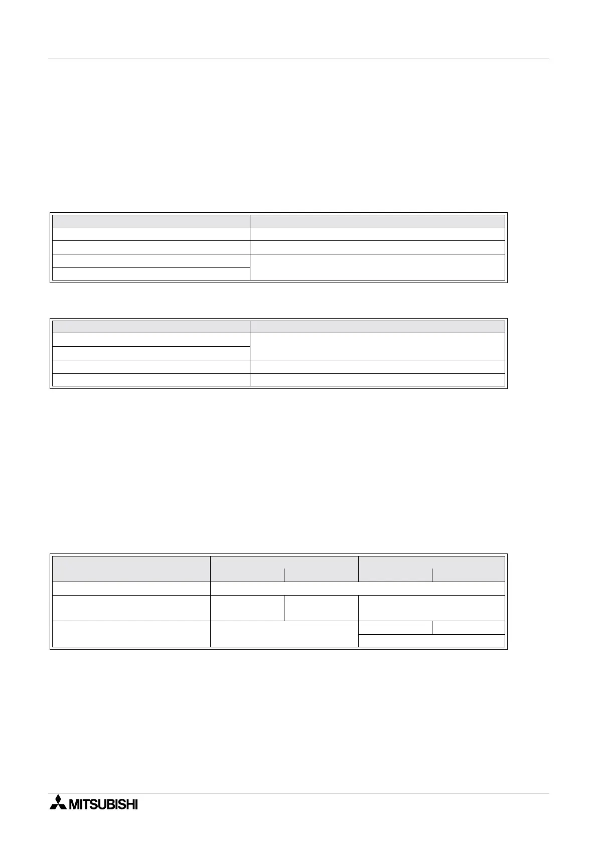
Summary
Circumstance Reaction
PLC's power is turned OFF All data is cleared
PLC's power is turned ON Certain devices are reset to their defaults see chapter 6
PLC is switched from STOP to RUN
Certain devices are reset to their defaults see chapter 6
PLC is switched from RUN to STOP
Circumstance Reaction
PLC's power is turned OFF
All data is cleared
PLC's power is turned ON
PLC is switched from STOP to RUN No change
PLC is switched from RUN to STOP Cleared (unless special M coil M8033 is active)
Memory type
Power PLC
OFF OFF ä
ää
ä ON STOP ä
ää
ä RUN RUN ä
ää
äSTOP
All devices backed by battery Not changed
Special M and D devices (8000 to
8255) and index registers V and Z
Cleared Default Not changed
All other devices Cleared
Not changed Cleared
Not changed when M8033 is set
 Loading...


