EasyManuals Logo

Mitsubishi FX1N Series Programming Manual

Mitsubishi FX1N Series
466 pages
To Next Page IconTo Next Page
To Previous Page IconTo Previous Page
Page #40 background imageLoading...
Page #40 background image
FX Series Programmable Controllers Basic Program Instructions 2
2-16
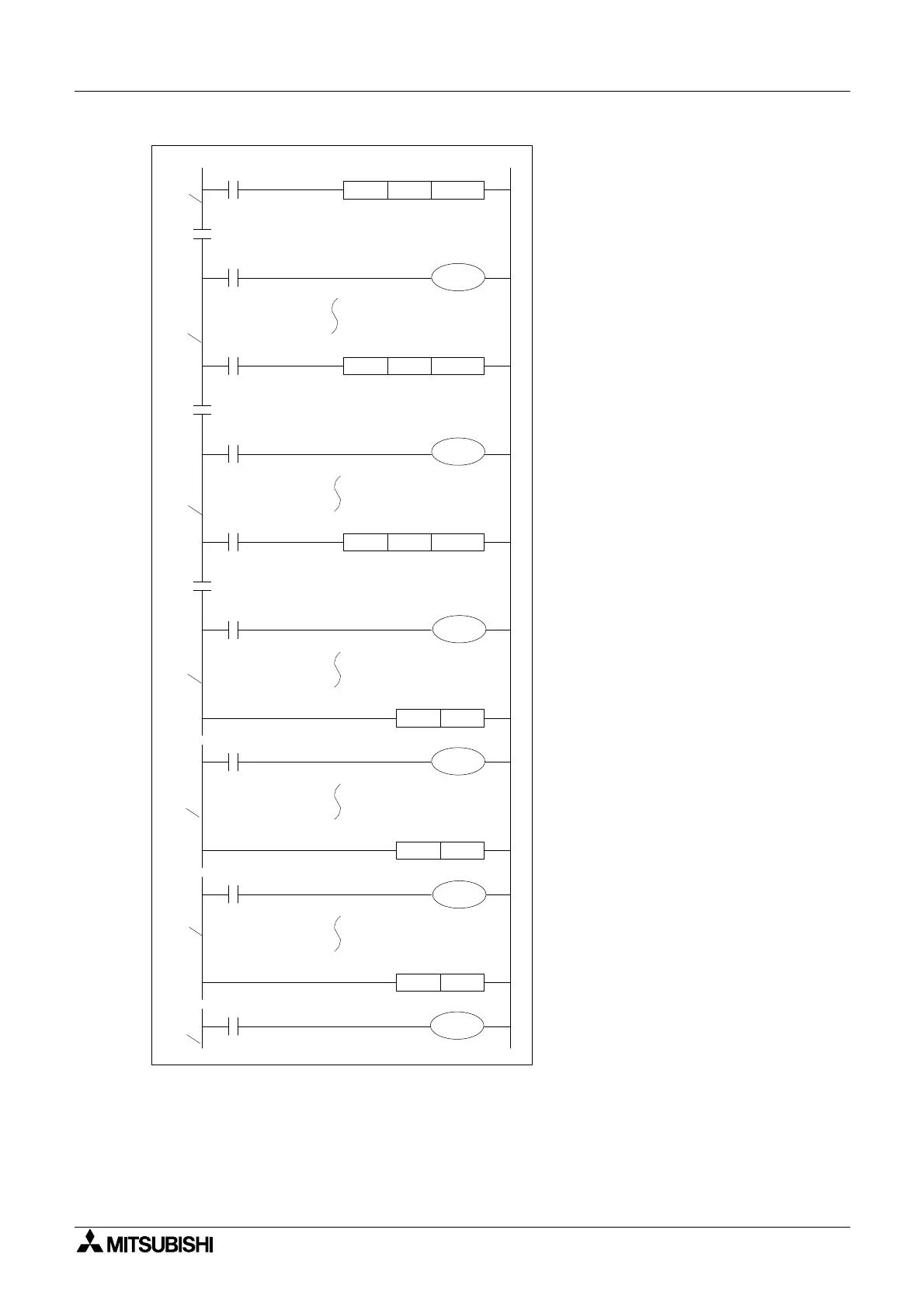
Nested MC program example:
Level N0: Bus line (B) active when X0
is ON.
Level N1: Bus line (C) active when
both X0 and X2 are ON.
Level N2: Bus line (D) active when
X0,X2 and X4 are ON.
Level N1: MCRN2 executes and
restores bus line (C). If the MCR had
reset N0 then the original bus bar (A)
would now be active as all master
controls below nest level 0 would reset.
Level N0: MCRN1 executes and
restores bus line (B).
Initial state: MCR N0 executes and
restores the initial bus line (A).
Output Y5 turns ON/OFF according to
the ON/OFF state of X10, regardless of
theON/OFFstatusofinputsX0,X2or
X4.
X0
X1
M100N0MC
MCR
M100N0
X2
X3
M101N1MC
M101N1
X4
X5
M102N2MC
M102N2
MCR
X6
MCR
X7
X10
D
C
C
B
B
A
A
Y0
N2
Y1
Y2
N1
Y3
N0
Y4
Y5

Table of Contents

Other manuals for Mitsubishi FX1N Series

Questions and Answers:

Question and Answer IconNeed help?

Do you have a question about the Mitsubishi FX1N Series and is the answer not in the manual?

Mitsubishi FX1N Series Specifications

General IconGeneral
Programming LanguageLadder Logic
Output TypeRelay, Transistor
Operating Temperature0 to 55°C
Power Supply100-240V AC or 24V DC
Program Capacity8K steps
Communication PortsRS-422
Data Memory8000 words
High-speed CountersUp to 6 channels
Expansion ModulesAvailable
Pulse Output2 points

Related product manuals